


ABCs of Power Amplifier Classes: Class B
Trading off amplifier linearity for better efficiency, why harmonic traps are needed, how push-pull architecture is used for broadband circuits, and the difficulties of its implementation at RF.

Hey, I’m Vikram 👋!
We continue down the path of amplifier classes. In Class B, you can boost efficiency by a lot, but you pay the price in linearity and drive strength requirements.
This post may be truncated in your email. Please view it on the web or on the Substack app.
In this article, we will look at the Class B amplifier.
This article is part of a series on power amplifier classes of operation. You can jump to any article using the links below.
Class B Operation (this article)
In this post, we will discuss the following as related to Class B amplifiers:
Amplifier operation
Efficiency (saturation, back-off)
Output harmonics
Load network (output match, harmonic traps)
Push-pull amplifiers
Read time: 12 mins
Class B Amplifier Operation
In the article on Class A amplifiers, we mentioned that the conduction angle is 360°. That is, the transistor is operating in the quasi-linear region for all phases of the input signal.
In Class B operation, we keep the transistor in the quasi-linear operation only for one-half of the input sinusoidal signal. For the other half, the transistor is kept in cut-off and does not provide amplification.
The conduction angle for a Class B amplifier is 180° or π radians.
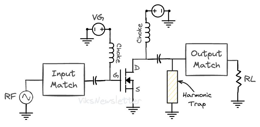
The schematic of a Class B amplifier is shown below, and is fundamentally the same as the Class A amplifier, with slight modifications.
The output load is modified to have a harmonic trap
The amplifier may be implemented in push-pull configuration (schematic shown later)
We will get into the reasons for both modifications later in this post.
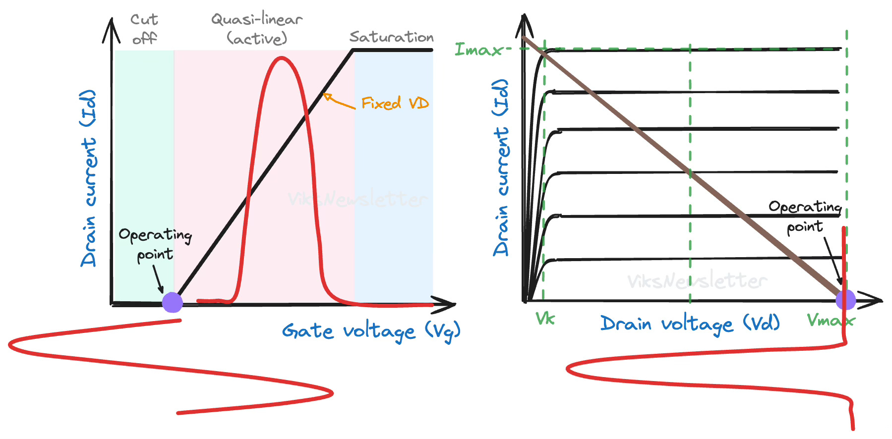
The main difference lies in where we choose the quiescent bias point for this amplifier class. The Q-point is chosen right at the edge of transistor cutoff. The transistor is driven into conduction by the positive cycle of the input signal, and remains in cut-off during the negative cycle.
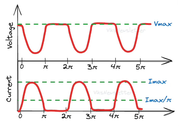
In Class B, the current waveforms in the drain of the transistor are easy to draw since it only conducts in positive half cycles. The voltage will remain at the Q-point VD, till the current flows through the transistor, at which point the voltage drops. Current and voltage are opposite in phase to each other.
We immediately get a sense that the efficiency should improve because the transistor is kept off half the time. But since only half the sinusoid is amplified, the output waveform is quite distorted degrading the amplifier linearity.
Class B Efficiency and Backoff
To calculate efficiency of this mode, like we did in Class A, we need a mathematical representation of the current and voltage waveforms. The drain current representation for 180° current conduction is given as
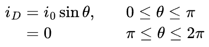
Unfortunately, this is where it gets hairy because half-sinusoids are not mathematically simple. We will deal with them using Taylor series expansions.
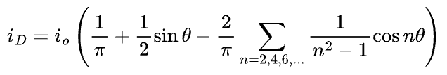
We will make two observations about the output current waveform to make this much simpler immediately.
It has no odd-order harmonic components
We will remove all the even-order components so we don't have to deal with them (using harmonic shorts, explained later)
Now, the output current equation is much easier to deal with.
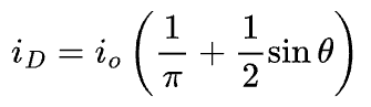
It consists of a DC component io/π and a fundamental frequency time-varying component (io/2)sinθ, which we can use to calculate load lines and efficiency.
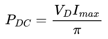
If the maximum amplitude of the half-sinusoid is Imax, then the DC component of the drain current is Imax/π. Remember that the equivalent DC current in Class A was Imax/2. Due to lower DC current, it is apparent that Class B is already more efficient. If the drain voltage is set at VD, then the DC power dissipation is
We can calculate the RF power delivered from the time-varying part of the drain current.
The maximum RF power delivered is when vo=VD and io=Imax, which gives
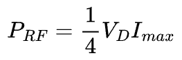
If you compare this with the output power from Class A, you will realize that Class B delivers the same output power as Class A. Which is cool if you think about it — Class B delivers the same output power while using lower DC power.
So what's the improved efficiency?

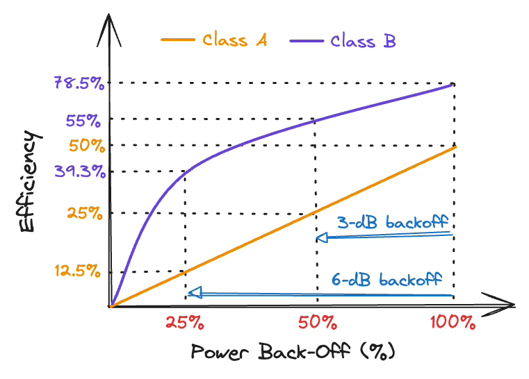
The maximum achievable efficiency of Class B operation is 78.5%
This is much better than the Class A value of 50% and we got this by turning off the transistor for half the cycle.
This almost feels like free lunch, but we pay in a couple of ways:
Linearity: The output waveform is not a faithful replica of the input signal anymore. This is not acceptable for some applications, especially those with complex time-varying waveforms like audio1. Thus, Class B is often implemented in a push-pull circuit configuration to recover the original sinusoidal waveform, at the cost of increased complexity.
Drive strength: Input signal to the amplifier needs to be much stronger to drive the output current positive peak to +Imax and the negative peak to -Imax (which will be cutoff anyway). In contrast, Class A amplifier current needs to only swing from 0 to Imax. If the output current has to have twice the peak-to-peak value, then the drive power requirement for Class B increases four-fold, or 6-dB, over a Class A amplifier. Needing higher drive strength means that the power-added efficiency (PAE) will drop, as will the power gain, which is not desirable.
If the input drive is backed-off by 6-dB, the input voltage signal swing drops by a factor of 2, and correspondingly the output current from the device drops by a factor of 2 (i.e., Imax/2). Thus, the output power also drops by a factor of 1/4th or 6-dB.
Even though the amplifier has a highly nonlinear output waveform, the symmetry of the current waveform allows Class B to act as a linear amplifier. Reduction of input power leads to linear reduction of output power.
The DC power consumption however only drops by half because VD is still constant, while DC current drops to Imax/2π. Thus, the efficiency of a Class B amplifier in 6-dB input power backoff is π/8 ⨯ 100% = 39.3%.
This is better than the 12.5% efficiency at 6-dB backoff from a Class A amplifier. In practice, there are other ways to engineer the output waveform to improve efficiency in back-off condition.
Output Harmonic Content
While the Class A amplifier provided faithful amplification with near-zero harmonic levels by operating in a quasi-linear region of the transistor, Class B operation generates significant harmonics at the output due to half the waveform being cut off.
We already saw from the drain current Taylor series that all odd-order harmonics will naturally have a zero value. But the even-order harmonics exist.
From the coefficients of the Taylor series, the magnitude of the fundamental and even-order harmonics of the drain current are shown below for up to the 10th harmonic.
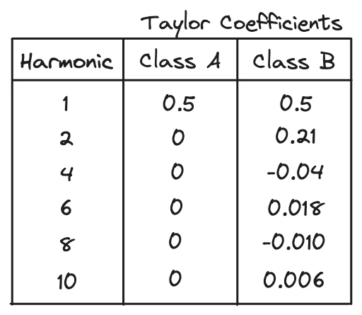
The most dominant harmonic is the 2nd harmonic, while the magnitudes of higher even-order components fall away according to the square of the order. The second harmonic amplitude is the same sign as the fundamental, which means it is in-phase with the fundamental component, while the fourth harmonic is out-of-phase with the fundamental component, and so on.
This second harmonic component, when correctly engineered in a PA, is useful in reducing the drive requirements to the PA. That will be a topic for another day, however.
Load Network and Harmonic Traps
Up until this point, we have still not discussed how the load line should be determined for a Class B amplifier. This is because the Class A load-line applies to Class B as well.
The maximum current Imax only flows through the device when the instantaneous VD is low, and relatively close to knee-voltage. Just like in Class A, the load line can be calculated as,

Once the optimal load is determined, the output matching network implements it by transformation from a 50-ohm termination, or from the input impedance of the following stage if the amplifier acts as a driver stage. Matching networks can be implemented with lumped passive elements or transmission lines.
Apart from this, remember that we assumed that all even-order harmonics were removed in the analysis of efficiency. The way this is implemented in practice is with a separate network called a harmonic trap.
A harmonic trap provides a short circuit at a harmonic frequency of operation, effectively removing its contribution to the output waveform.
Ideally, the harmonic trap does not interfere with the output match at fundamental frequency, but this is rarely the case in practice. The interactions will need to be accounted for via circuit simulation.

In integrated circuit designs, harmonic traps are implemented as on-chip LC-resonators, or off-chip with surface-mount components. In hybrid designs (discrete transistor on a printed circuit board, or PCB), a widely used approach is to use a quarter-wavelength (λ0/4) (at fundamental f0) short-circuited stub. This provides two main advantages:
It presents an open-circuit at the fundamental frequency f0, making it invisible to the output matching network.
It presents a short at 2f0, 4f0, etc., effectively shorting out multiple even order harmonics.
In reality, the bandwidth of the harmonic trap implemented with stubs is eventually limited, with higher characteristic impedance lines providing greater bandwidth. As a result, you will often see harmonic traps implemented as narrow traces meandered on a PCB to save space, in many hybrid PA designs.
Push-Pull Topology
As we mentioned earlier, the Class B amplifier output is still highly nonlinear due to only the positive half-sinusoid being amplified. A clever way to improve linearity is to use the push-pull topology for Class B amplifiers.
A push-pull amplifier design recovers the linearity degradation in Class B amplifiers by amplifying the negative half-sinusoid, and combining it with the amplified positive half-sinusoid, to recreate a faithful amplified replica of the input signal, at the output of the amplifier.
The figure below shows the circuit implementation of a push-pull amplifier.
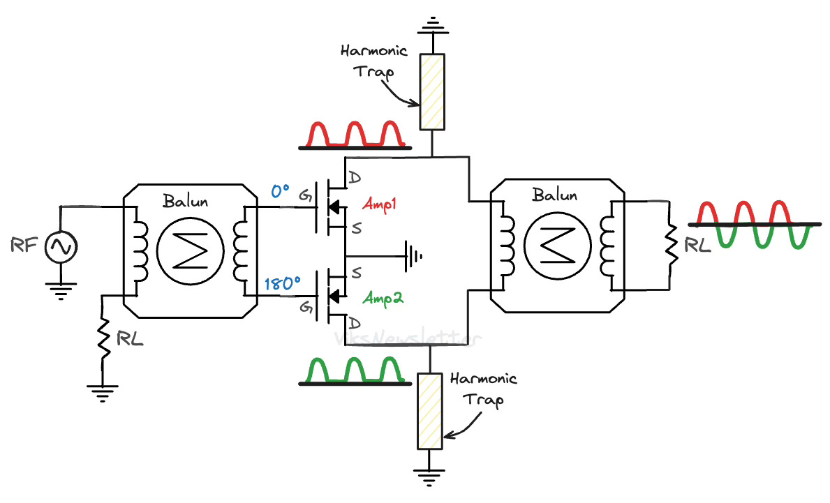
The working principle of a push-pull amplifier is as follows:
It uses two Class B amplifiers, of which, only one of them actively amplifies the signal at any point in time (like a tandem bicycle with only one person pedaling at a time.)
The input has a balun (balanced-unbalanced) which divides the input signal into two paths which are 180° offset in phase from each other.
Amplifier 1 only amplifies the positive half-sinusoids.
Amplifier 2 only amplifies the negative half-sinusoids (which are actually positive half-sinusoids after 180° input phase shift.)
The output also has a balun that combines the outputs of amplifiers 1 and 2. Because there is again a 180° shift between the paths, the reconstructed signal is assembled as a pure sinusoidal wave.
The output power and efficiency assuming lossless baluns are the same as a single Class B working on its own because only one of them is amplifying at any given time.
There are two major benefits to using the push-pull amplifier topology:
Wideband operation: If a wide bandwidth balun can be implemented at the input and output, the push-pull amplifier configuration is capable of very broadband operation. If no harmonic traps are implemented at the outputs of the Class B amplifiers, the push-pull configuration is capable of reconstructing the full input signal at the output, even if it's not sinusoidal. This makes this topology very attractive when high linearity is needed is needed over a broad bandwidth of operation.
High input/output impedance: The input and output impedance of the balun-connected amplifier stages is two-times that of a single ended amplifier. For example, if Ropt is the load-line needed for a single-ended PA, then the push-pull implementation requires 2Ropt. This is a great advantage for high power PAs where the device size is so massive that Ropt is less than 1 ohm. Using a push-pull approach boosts that value so it becomes easier to design matching networks.
Difficulty of Push-Pull at RF
Unfortunately, the use of push-pull amplifiers is only widely used at frequencies below about 300 MHz. At GHz frequencies, there is one major limitation that limits the use of push-pull amplifiers: balun loss.
At lower frequencies, push-pull implementation is possible due to the availability of toroidal ferrite-core balun-transformers (up to 30 MHz) and coaxial transmission-line based balun-transforms (up to 400 MHz). Check out this 700W amplifier from Microsemi that operates from 1 - 52 MHz (that’s over a decade of frequency!) and utilizes primarily ferrite based baluns at the input and output.
Baluns are notoriously difficult to design for high power PA applications at GHz frequencies because dissipative losses wipe out any efficiency advantages obtained from a Class B implementation. That is not to say researchers have not tried to implement push-pull amplifiers at GHz frequencies. In 2020, Maktoomi et al. implemented a microstrip balun design with about 3-dB insertion loss and still managed to design a 1.8-2.7 GHz push-pull PA with 60-75% efficiency.
As a final word, the push-pull topology is not only restricted to Class B amplifiers. The idea can be applied to any reduced conduction angle amplifier to improve the overall linearity and bandwidth of operation.
References
Inder J. Bahl, Fundamentals of RF and Microwave Transistor Amplifiers, Wiley & Sons, 2009.
Steve C. Cripps, RF Power Amplifiers for Wireless Communications, Artech House, 2nd ed.
M. H. Maktoomi, et al., “A Wideband Isolated Real-to-Complex Impedance Transforming Uniplanar Microstrip Line Balun for Push–Pull Power Amplifier,” IEEE Trans. Microwave Theory Techn., vol. 68, no. 11, pp. 4560–4569, Nov. 2020.
S. C. Cripps, "The evolution of the push-pull RFPA," 2015 IEEE MTT-S International Microwave Symposium, Phoenix, AZ, USA, 2015.
If you like this post, please click ❤️ on Substack, subscribe to the publication, and tell someone if you like it. 🙏🏽
If you enjoyed this issue, reply to the email and let me know your thoughts, or leave a comment on this post.
We have a community of RF professionals, enthusiasts and students in our Discord server where we chat all things RF. Join us!
The views, thoughts, and opinions expressed in this newsletter are solely mine; they do not reflect the views or positions of my employer or any entities I am affiliated with. The content provided is for informational purposes only and does not constitute professional or investment advice.
Class B and its related output distortion may be acceptable for some RF applications because we only need to recover the envelope of the RF carrier signal to recover the baseband information used for modulation. There is no real need to perfectly reconstruct the carrier waveform. For audio, the exact waveform is very important.
Nice! It was interesting to see this in RF, all my class B designs were for audio. In audio range it is normal to tinker with bias to have a complementary pair partially on at the crossover and then use feedback to control the harmonics. There used to be lots of arguments about whether you could hear the distortion from the varying transfer function even after feedback.
So with the balun you do not need to find complementary pair devices, making matching easier, which is nice. I suppose old vacuum tube amps did that even for audio when they did class B.
Shouldn't the push-pull output balun be split with a central tap to the power supply voltage? Your push-pull circuit connects everything to ground, no obvious source of power.
OIC, you have just left out the chokes on each side, for simplicity, referring back to see where power came from in the single-sided design. I guess that keeps the balun simple and they are likely the more expensive kind of inductor.
Thank you. It is a very good explanation on amplifiers. I think you should mention that the expansion of the current is using Fourier series.