The Image Problem in Superheterodyne Receivers
Superheterodyne receivers can convert two different radio signals to the same intermediate frequency and destroy the received signal unless the system is designed with care and trade-offs are made.
Hey, I’m Vikram 👋! We’ve reached 2,500+ subscribers. Thanks for reading!
Based on feedback from readers, I’m considering designing a mini-course that can teach RF concepts in byte-sized videos. I intend for these videos to be short, loaded with information, and engaging; the goal is to make it self-paced and easy to complete. Reply to this email with your ideas for topics!
This post may be truncated in gmail, please read it in the browser. Click here if you’d like to sponsor this newsletter. Click ❤️ on Substack if you enjoyed it, leave me a comment or share this article. Word of mouth helps grow this newsletter! 🙏
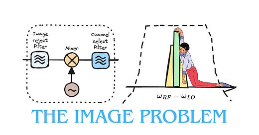
In a previous article, we looked at the superheterodyne receiver architecture and the story of Armstrong, Sarnoff and RCA. This architecture faces a big challenge: the problem of image frequencies.
Here is a summary of what we will learn in detail:
A mixer is used in a receiver to convert the RF signal to an intermediate frequency (IF) by multiplying the RF signal with a local oscillator (LO) signal.
Negative frequencies are required to represent real signals, and play an essential role in system design.
The LO signal can be lower or higher than the RF signal and the mixer has low-side or high-side injection, respectively.
When the LO signal is right in between two RF signals, they both convert to the same IF. This is called the image problem.
Choice of IF is a trade-off between rejection of image vs. channel selection.
Read time: 10 mins
The Mixing Operation
The heart of the superheterodyne receiver lies in the conversion of the amplified RF modulated signal into a lower intermediate frequency (IF) by the mixer. At lower frequencies, amplifiers are easier to design and filters have more selectivity. This is why the superheterodyne works so well.
The mixing operation in the time domain is simply an analog multiplication of two signals: the RF modulated signal and a local oscillator (LO) signal. In the frequency domain, this is a convolution of the two signals.
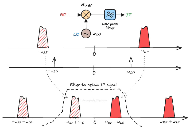
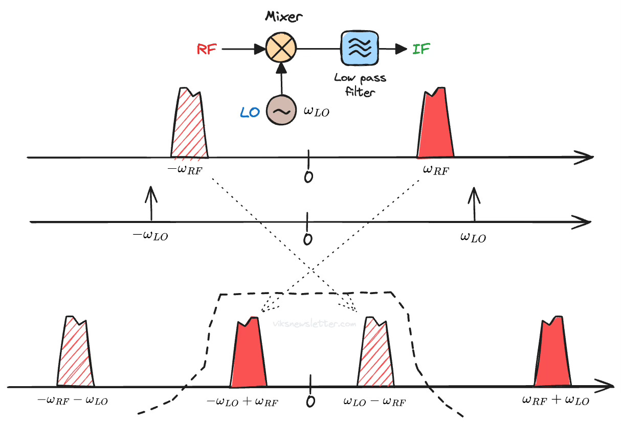
Let's say that the RF and LO signals are both cosines with angular frequencies ωRF and ωLO (ωLO < ωRF). As we will see later, there is a good reason we use cosines. The multiplication of these cosines results in four distinct frequency products. The sum and difference between the two signals in the positive and negative frequency domains.
The concept of negative frequency is confusing, and we will get to that in the next section. For now, just know that a real signal needs to have positive and negative frequency components which are equal.
The modulated RF signal is not a pure cosine, and has some bandwidth associated with it. The process of mixing moves the whole spectrum of the RF signal to the new sum and difference frequencies.
The components up-converted to higher frequencies are easily filtered out with a low pass filter. This just leaves the down-converted components at an IF frequency lower than the original signal. This is common in receivers. Instead, the high frequency components could be retained by appropriate filtering. Such up-converting mixers are common in transmitters.
The frequency translation looks something like the figure below. The negative frequency components are shown with a line fill to distinguish them from the positive frequency components.
In reality, we want to convert a particular RF channel of fixed bandwidth to IF. We have two options:
Have a fixed LO signal, which results in different IF.
Have a variable LO signal, which results in fixed IF.
Of these choices, option two is the better one. It is much more challenging to design low loss, high rejection IF filters that are also tunable. A variable LO is much easier to generate using a highly accurate and stable frequency synthesizer.
Let's make a short detour to understand negative frequencies before we proceed with superheterodyne mixing and its associated problems.
The Need for Negative Frequencies
To many (including myself until I looked into it) the concept of negative frequency seems almost... unreal. After all, when we measure a sinusoidal tone, we only see one line on the spectrum analyzer screen. But, we are looking at only half the story.
To see the whole picture, we need to look at a complex sinusoid. In its polar form, it is represented as,
Thanks to Swiss mathematician Leonhard Euler, we can represent this quantity in rectangular axes (x=real, y=imaginary), using
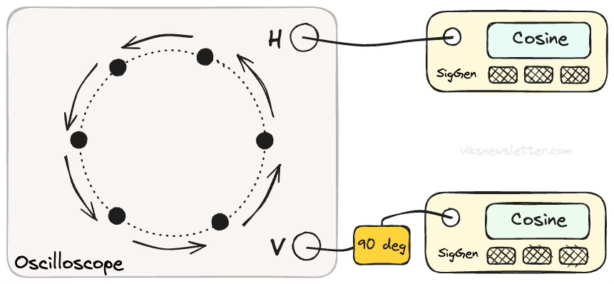
This immediately tells us how to create a complex sinusoid in the lab, and transmit it to your buddy in the neighboring office. This is what you do:
Take two sinusoidal signal generators set to the same frequency f0.
Phase shift one of the signals by 90 degrees.
Connect cables to both the original and 90 degree shifted signals.
At the other end, connect them to the horizontal and vertical channels of an oscilloscope, respectively.
You will see a spot rotating anti-clockwise on the screen as shown below.
For more complicated signals, you can apply a filter that shifts each sinusoidal component by 90 degrees. Such a filter is called a Hilbert Transform.
If you look at this in three dimensions, with time as the third axis, what you see is a helix that is propagating forward with time. Thus, the complex sinusoidal signal can be broken down into what are called its in-phase and quadrature components. This is a concept you will keep running into when you learn about RF systems.
Back to the case of a single cosine signal. Using Euler's identity, a cosine signal can be represented as
There is the negative frequency we were looking for. Here is how you interpret it.
Your distracted friend accidentally swapped the sine and cosine signals. As a result, the spot on the oscilloscope now goes clockwise, instead of anti-clockwise. In three dimensions, this would appear as a helix spiraling backward in time. That's pretty much all there is to negative frequency - a reversal of direction.
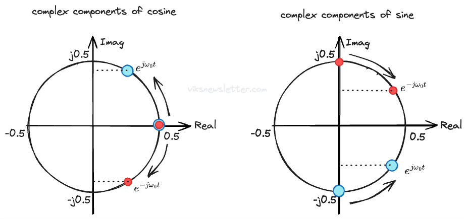
In polar form, a cosine wave has a positive frequency sinusoid rotating anti-clockwise, with a negative frequency sinusoid rotating clockwise, such that their imaginary parts always perfectly cancel.
How about a sinusoidal signal? Euler's identity tells us,
The j-operator means you need a 90 degree shift, and the negative sign implies an additional 180 degrees. In the complex plane, you have the positive frequency at 270 degrees and negative frequency at 90 degrees, and they rotate in a way that the imaginary parts perfectly cancel, giving you a pure sine wave.
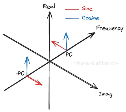
We can now think of how this is all represented in the frequency domain. The components of a sine and cosine signal are shown in the figure below. The cosine just has two components with the same sign on the real axis. The sine has two components with opposite signs on the real axis.
Finally, you can see why almost all technical analyses start with cosines. They are just easier without the j-operator and negative sign. Hopefully it is now clear that we need negative frequencies to fully represent an arbitrary signal.
Low- vs. High Side LO Injection
The example of downconversion in the first section imposed that ωLO is lower than ωRF. This is called low-side injection. We could have generated similar down-converted IF signal by having ωLO > ωRF. This is called high-side injection. The figure below shows the down-converted spectrum for high-side injection.
Notice that the spectrum is mirrored compared to the low-side injection case.1 This is quite important, and needs to be corrected by the digital signal processor. If there was another down-conversion step to a second IF using high-side injection, then this spectrum will mirror again, restoring the correct spectral shape.
As an aside, this is only an issue because the signal spectrum is not symmetric - which is often the case with single sideband modulation. If we used both sidebands to have a symmetric baseband signal, as is the case with double sideband modulation, then this flipping of the spectrum would not be of concern.
The choice of low- vs. high-side injection depends on the system design and the occupancy of the spectrum around the desired signal. Here are some advantages of using high-side injection:
Enhanced filter rejection: Since the LO is located at a frequency higher than the RF signal, good filters can be designed to select the IF signal and reject higher frequencies.
Improved linearity: Since the LO is much farther away from the IF, there are lower LO-feedthrough problems arising from leakage of LO into IF.
Lower noise: Designing the LO at a higher frequency makes it less susceptible to flicker (1/f) noise and other low frequency spurious signals.
The Problem of Images
So far we have only considered a single RF channel being down-converted to lower frequencies. In reality, this is rarely the case. There are neighboring channels on either side of the desired RF channel that also get down-converted.
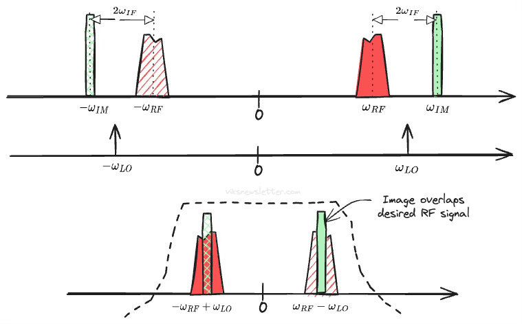
As a special case, consider the situation where the LO is located exactly between the desired signal and undesired channel. In the example below, the LO is used in high-side injection to down-convert the desired RF channel. Unfortunately, there is an another channel for which the same LO acts as low-side injection.
When the spacing between channels is exactly twice IF, both the desired and image channels down-convert to the same frequency. The undesired channel that overlaps the desired one is called the image. If the image channel has a high signal level, it can completely swamp out the desired signal.
Image Filtering and Choice of IF
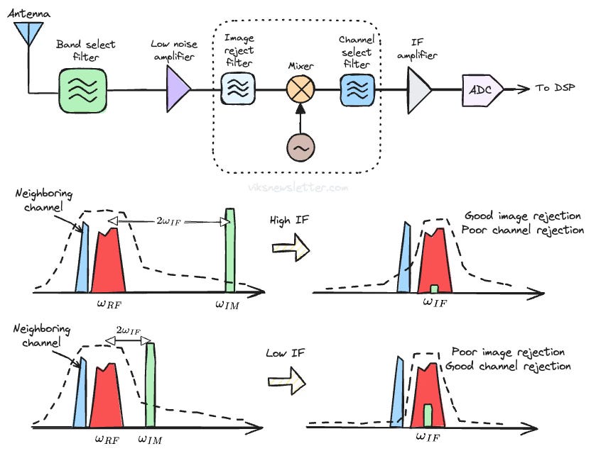
The classical method to avoid the image problem is to filter it out preemptively. A bandpass filter is placed before the mixer to remove the image frequency, called the image reject filter.
The effectiveness of this approach depends on the trade-off between the IF frequency and channel selection.
Choose a high IF.
Image filtering is easy because the filter has sufficient rejection at twice the IF frequency, where the image is located. But, high IF makes it difficult to select the proper channel using a channel select filter because it may not have sufficient rejection to suppress the neighboring channel.
Choose a low IF.
Channel selection becomes easy because highly selective filters can be designed at lower frequencies. The rejection of image frequency becomes harder due to limited rejection of the image-reject filter at image frequency.
Suppose there were no interferers, like in space applications, would we still use image-reject and channel select filters? The answer is yes. Even if no signals are present, there is still thermal noise to deal with. Using filters to suppress noise improves SNR of the system.
The metric most commonly use to measure the level of image rejection is called image rejection ratio (IRR). IRR is defined as the ratio between the IF signal level from the desired signal, to the IF signal level produced from the image frequency. We want this ratio to be as high as possible, and is often expressed in decibels (dB).
There are ways to circumvent the trade-offs imposed by the image reject superheterodyne architecture described here. They include direct downconversion, dual downconversion and image reject architectures, among others. That will have to wait for now.
📚 References
B. Razavi, RF Microelectronics 2nd ed., Chapter 4.2.
R. Lyons, Understanding Digital Signal Processing’s Frequency Domain
Many thanks to my friend and colleague Aram Akhavan for discussions on this. We spent an evening working out what the spectrum reversal means in great detail. We will get into it in a future newsletter.
The views, thoughts, and opinions expressed in this newsletter are solely mine; they do not reflect the views or positions of my employer or any entities I am affiliated with. The content provided is for informational purposes only and does not constitute professional or investment advice.


Great visuals!