ABCs of Power Amplifier Classes: Class AB and C
How operating in Class AB can overcome cross-over distortion in Class B push-pull amplifiers, getting near 100% efficiency in Class C, and understanding design tradeoffs in Classes A, B, AB, and C.
Hey, I’m Vikram 👋!
What happens in amplifiers that have lesser conduction angles than Class A and Class B? This post addresses Class AB and Class C amplifiers. We’ll round up this post with a comparison of all four amplifier classes.
This post may be truncated in your email. Please view it on the web or on the Substack app.
In this article, we will look at a few more conduction angle based classifications, namely Class AB and Class C amplifiers. In contrast to previous posts, we will deal with these classes "loosely" because the more rigorous calculations of efficiency and power back-off are hard to do for arbitrary conduction angles.
This article is part of a series on power amplifier classes of operation. If you want to read the other articles, check out the links below:
Class AB, C Operation (this article)
In this post, we will discuss the following:
Cross-over distortion in Class B
Class AB operation
Class C operation
Summary of Amplifier Classes
Read time: 10 mins
Cross-over Distortion
We'll approach Class AB amplifiers from the perspective of cross-over distortion in Class B push-pull amplifiers.
In the last article, we looked at the push-pull topology that used two amplifiers with 180° phase shift between them to reconstruct the output signal with minimum distortion. The operation is analogous to a tandem bicycle, where only one person is pedaling at a time to keep it moving. We also discussed the need for increased drive strength of the input signal to keep the operation in Class B.
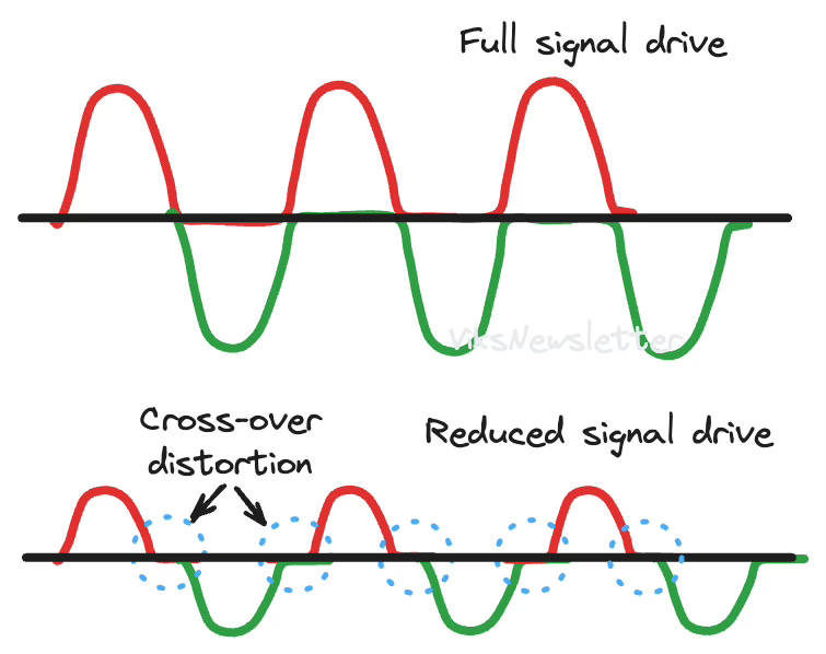
What happens if the input level drops? We calculated 6-dB backoff efficiency of Class B to be 39.3%, but what happens to linearity of the output signal?
If you look at the waveforms at weaker input drive, you notice that there is a portion of the signal cycle where neither amplifier is conducting resulting in zero output signal. This phenomenon is called cross-over distortion where the output signal is no longer resembles an amplified version of the input signal due to neither amplifier working at the zero-crossing point. Going back to our analogy, this corresponds to neither cyclist pedaling. Or if you prefer an olympic sport example, the baton is passed between runners but neither one is running.
Class AB Operation
Here is the quick fix to the problem.
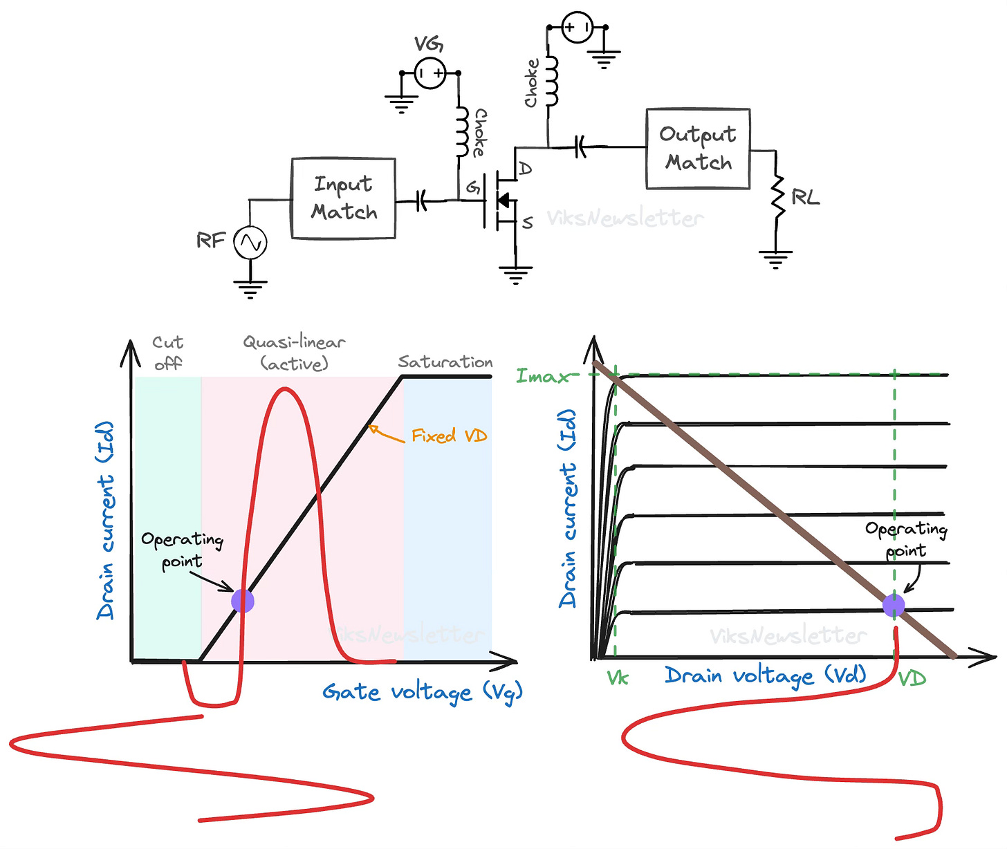
Change the bias point of the transistor so that when the input signal drops below zero, the transistor is still conducting and amplification continues.
In our tandem bicycle analogy, if one cyclist stops pedaling, the flywheel keeps the wheels moving till the other cyclist picks up the pedal. In contrast, pure Class B operation is more like a fixie tandem bicycle where it slows down if either one stops pedaling.
What this means from a Q-point perspective is that the transistor should be biased above cutoff but not so much that it becomes a Class A amplifier. The transistor conducts for the whole positive half cycle, and also during some part of the negative half cycle. How much of the negative cycle is conducting depends on how far the Q-point is from Class A or B.
If the bias point is close to Class B, then the only a small portion of the negative half cycle will conduct, resulting in higher distortion and better efficiency. Conversely if the bias point is close to Class A, then the transistor conducts almost the entire negative half cycle, resulting in lower distortion and lower efficiency.
In a Class AB amplifier, the Q-point is in between Class A and Class B, and the conduction angle is between 180° and 360° (or π and 2π radians.)
If you want to have a visual understanding of how operating in Class AB mode fixes the issue of cross-over distortion, then check out this awesome video.
Efficiency and Power Back-off
If the bias point of a Class AB amplifier is between that of Class A and Class B, we can also infer that the efficiency of Class AB is between 50% and 78.5%. But unlike Class A or B, there is no specific condition that classifies it as Class AB. As we discussed in the last section, the choice of bias condition results in a trade-off between efficiency and linearity.
If you lower the level of the input signal, Class AB amplifiers can still provide linear amplification, especially if the Q-point is closer to Class A operation. But unlike Class A or B, where a 3-dB drop in input level results in a 3-dB drop in the output signal, a Class AB amplifier does not drop its output by 3-dB because is not a linear amplifier.
This is due to the fact that the conduction angle and Q-point in a class AB amplifier is a function of the drive level. The gain of the amplifier, and consequently the output power depends on where the amplifier is biased at any given level of input signal.
Output Load and Power
To the first order, the loadline of a Class AB amplifier can be retained from Class A or Class B. In practice, the increased conduction angle (over Class B) results in a higher fundamental component of current (we will calculate this later in this article.) Thus, the optimal resistive load required for a Class AB amplifier is about 10% lower than its first order (Class A/B) value and consequently, the gain is a few tenths of a dB higher than its Class A and B counterparts.
Unlike Classes A and B which had no output odd-harmonics due to the symmetric nature of the waveform, Class AB amplifiers have both odd- and even-harmonics at the output. A significant amount of research has been performed on the best impedances to present at harmonic frequencies to optimize output power, linearity, or a balance of both.
As an example, students from the University of Bristol won the Student Design Competition at the 2016 International Microwave Symposium for designing a Class AB power amplifier that used the distortion of the output waveform to cancel out the weak nonlinearity of the transistor itself by both tweaking the gate-bias voltage and the third-harmonic impedance, which turns out is particularly significant in Class AB PAs. The cancellation effect presented a "sweet spot" where the third-order intermodulation products at the output were very low, resulting in improved PA linearity.
Class C Operation
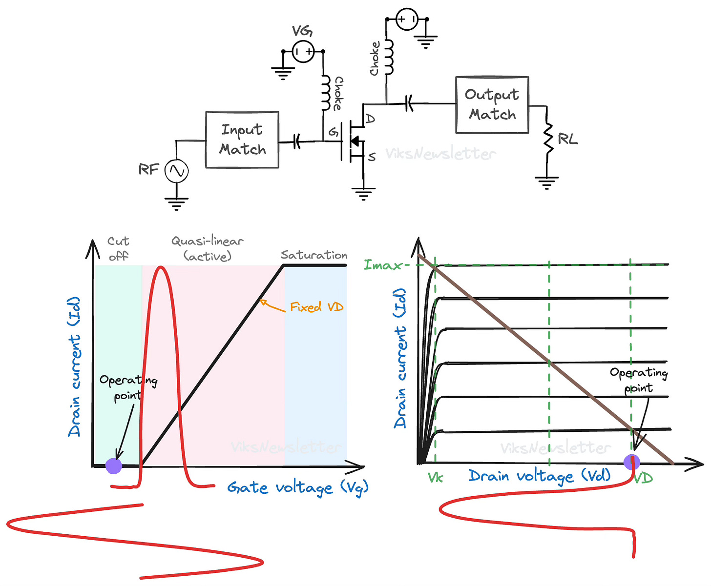
Class C operation is the case when conduction angle is reduced further compared to Class B. In the drain-current, gate-voltage curve below, the device is biased deep in the cut-off region so that only a sufficiently large input signal swing can turn on the device for conduction. The input drive should be even stronger than Class B so that the output current can swing up to the maximum value of drain current Imax.
In Class C operation, the conduction angle is between 0° and 180° (or between 0 and π radians.)
Class C amplifiers have several drawbacks that limit its usefulness at RF frequencies:
The output signal is highly distorted and requires the use of linearization techniques to make Class C operation useful.
While you can achieve very high efficiencies, the output power is significantly lower.
Due to its highly nonlinear output waveform, amplitude modulation techniques cannot be used with such amplifiers.
For a given output power, the device needs to handle larger currents than Class A or B operation, especially as conduction angle is reduced.
For larger current, active device size used is large, which restricts its operating frequency and bandwidth to low values.
In addition, the active device needs to be shut off for most part of the input sinusoidal signal, which implies that the transistor should have low leakage to realize high efficiencies. This makes bipolar transistors more suitable for Class C compared to MOS devices, which generally have high gate leakage (depending on gate length of course.)
Highly battery sensitive applications that do not require high output power might be suitable applications for Class C. It is not used often because other high efficiency techniques exist with better performance. We will look at Class C only briefly for the sake of completeness.

Efficiency and Power
Instead of calculating power and efficiency from first principles like we did for Class A and B amplifiers, we will simply list out some expressions1 here and find out where Class C lies in related to Classes A, B and AB.
For a conduction angle of 2ϕ, the maximum DC power consumption is given by,
the maximum RF power is given by,
and the drain efficiency is given by the ratio of the above two equations by,
The DC and RF power values are normalized to Class A, and we can evaluate these equations as a function of conduction angle quite nicely.
As the conduction angle decreases, the DC power consumption drops and so does the delivered RF power. For low conduction angle Class C operation, the efficiency reaches nearly 100% but the low RF output power makes this class undesirable, especially with its associated highly nonlinear waveform.
From this plot, we can also justify why Class AB is a popular class of operation. It provides even slightly higher RF power compared to Class A, gives good efficiency (60-70%) and has a moderate level of output distortion resulting from reduced conduction angle.
Summary of Amplifier Classes of Operation
This is a good time to put together all our learnings so far about amplifier classes, and summarize some results.
The operation of an amplifier in different classes depends on how the quiescent bias point is selected. The figure below shows how the Q-point for each class is chosen.
Depending on what fraction of the signal cycle the active device conducts, the output current flows only for part of the overall sinusoid. Based on the angle of conduction, the output waveforms progressively get more nonlinear -- with Class A being most linear and Class C being most nonlinear.
As the conduction angle is reduced, the input of the amplifier must be driven harder to achieve good efficiencies. This is usually bad for gain and power-added efficiency because transistor gain is a scare resource at RF frequencies.
Depending on the conduction angle, the table below shows a numerical summary of the theoretical DC dissipation, RF power delivered and drain efficiency of various classes of power amplifier operation.
If you want see some amplifier designs for each class, then check out this excellent video from Keysight Technologies. You can even download workspaces to try it out.
This article concludes the basic classes of amplifier operation that are simple to understand based on conduction angle. From now on, we will enter the realm of switched power amplifiers, harmonic load control, supply modulation and a whole assignment of seemingly random letters for operating class.
I'm not even sure how I'm going to go about it at the moment. As always, its best to embrace the chaos and enjoy the ride.
See you in the next one.
References
Inder J. Bahl, Fundamentals of RF and Microwave Transistor Amplifiers, Wiley & Sons, 2009.
Steve C. Cripps, RF Power Amplifiers for Wireless Communications, Artech House, 2nd ed.
If you like this post, please click ❤️ on Substack, subscribe to the publication, and tell someone if you like it. 🙏🏽
If you enjoyed this issue, reply to the email and let me know your thoughts, or leave a comment on this post.
We have a community of RF professionals, enthusiasts and students in our Discord server where we chat all things RF. Join us!
The views, thoughts, and opinions expressed in this newsletter are solely mine; they do not reflect the views or positions of my employer or any entities I am affiliated with. The content provided is for informational purposes only and does not constitute professional or investment advice.
For more details, read Chapter 8.4 in Bahl's "Fundamentals of RF and Microwave Power Amplifiers" to get a general idea how these equations come about, but there are typos in the equations and the numbers don’t come out right. If you notice any issues with my equations in this article, write to me and let me know!


Hey Vik - if a designer doesn't care too much about linearity and wanted to optimize for 1. efficiency and 2. power, are there other more exotic topologies to consider outside of just class B?