Understanding How Electric Vehicles Convert Battery Power Into Propulsion
How IGBT and SiC based traction inverters use power from the lithium ion battery pack to drive the motors using sinusoidal pulse width modulation.
Technological innovation and falling metal prices have dropped the cost of lithium ion batteries by 97% since 1990, and are expected to still go 50% lower by 2026. Recently, Nissan announced that they aim to achieve production cost-parity between electric vehicles (EVs) and vehicles with conventional internal combustion engines by 2030.
While battery technology is the heart of an EV, the mechanism of power conversion to drive the motors and provide propulsion is part of its core electronics. It requires the use of special power electronics circuits and unique semiconductor devices capable of withstanding hundreds of volts and sustaining hundreds of amperes of current simultaneously. Impressive innovations in power devices have played an important role in the electrification of transportation.
This article will explore in detail how power from the batteries are converted into kinetic energy that drives the motor, and the power circuits involved in doing so.
Here is a table of contents:
EV powertrain architecture
Traction motor operation
Traction battery design
Lithium ion batteries
Series-parallel configurations
Traction inverter design
2-level voltage source inverter
Sinusoidal pulse width modulation
Read time: 13 mins
EV Powertrain Architecture
In its simplest form, an EV is a bunch of wheels attached to a motor that is driven by a giant battery.
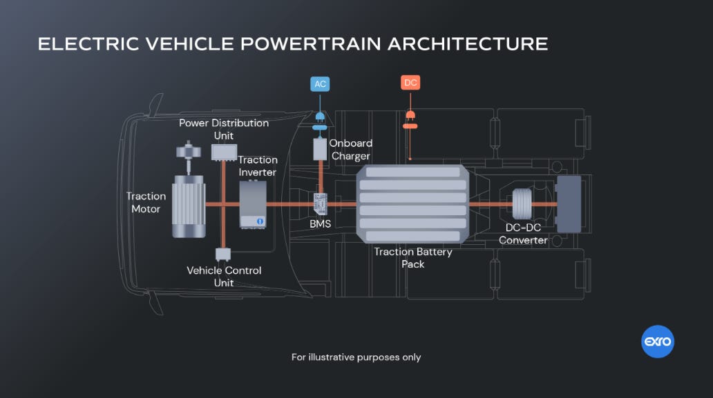
The figure below shows the general architecture of an electric powertrain. The traction battery pack is the heart of the system and provides a DC voltage that powers the entire vehicle. The output of the battery pack is not directly useful and must be converted into other forms more appropriate for its function. Let’s briefly discuss the main blocks in the picture.
Traction Battery Pack + BMS: A giant array of hundreds of lithium-ion (Li-ion) batteries hooked up in series-parallel configuration that produces either 400V or 800V of DC voltage. The total energy stored is often in the range of 80—120 kWh. The battery management system (BMS) is a power electronics circuit whose function is to ensure the reliable and safe operation of the traction battery.
Traction Motor: This is an electric 3-phase motor driven by an alternating current whose drive shaft is connected to the wheels, and generates the actual propulsion of the vehicle. The term “traction” used to describe this motor differentiates its ability to overcome inertia to cause movement, compared to other motors not directly used for motion.
Traction Inverter: This is an inverter circuit that converts the DC voltage provided by the traction battery into an AC voltage that drives the traction motor. This is implemented with power transistors that need to withstand anywhere between 600V and 1200V of instantaneous voltage across its terminals.
Onboard Charger: This block rectifies the AC power available at the wall outlet into DC power that is used to recharge the battery. AC chargers are generally lower power with longer charging times, while DC fast chargers offer higher power without the need for the rectifying function of the charger. The BMS appropriately handles the charging of the battery from AC or DC sources.
DC-DC Converters: The large voltages from the traction battery cannot be utilized for other on-board electric systems such as air-conditioning, entertainment systems, and other intelligent electronics that use much lower voltages. The voltage from the traction battery is stepped down by a DC-DC (often called “buck”) converter into 48V or 12V and used to power traditional car batteries.
There are other blocks that manage the distribution of power and vehicle control that we won’t get into. Our main goal is to understand how energy from the traction battery is converted into kinetic energy in the motor for EV propulsion.
Traction Motor Operation
I know I don’t often think about how motors work, so here is a short refresher if you need one. Feel free to skip this part if you already have an understanding of motor operation.
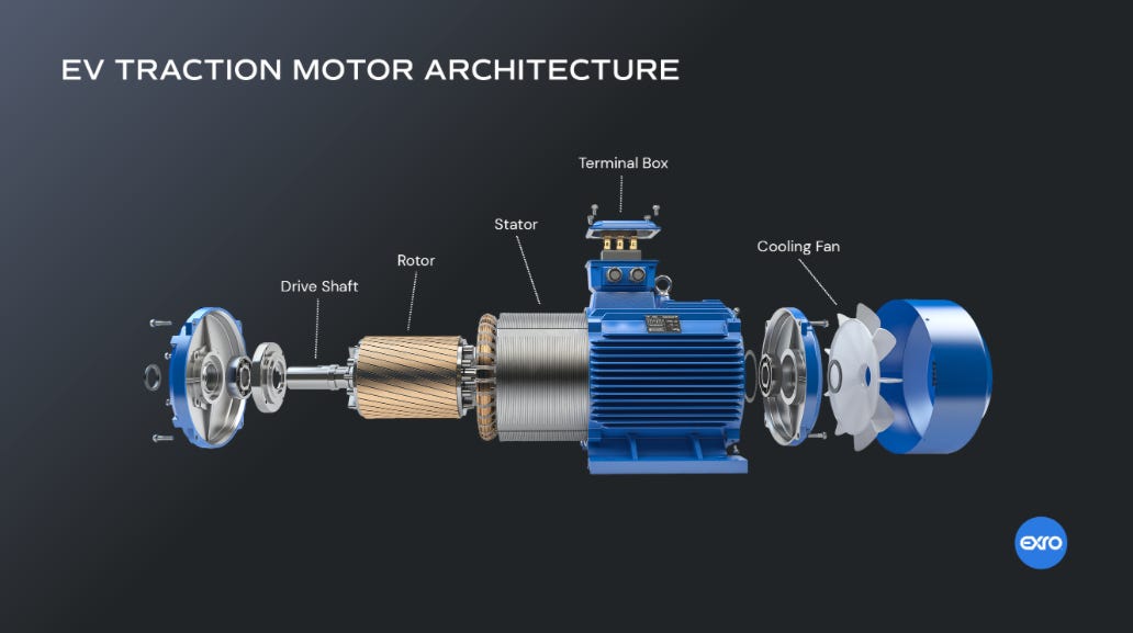
A motor converts electrical energy to mechanical energy through the property of electromagnetic induction and has two parts to it:
Stator: It is the stationary part of the motor that contains a ferromagnetic material like silicon steel or iron with wound wires called the field winding. Its function is to produce a rotating magnetic field.
Rotor: It is the rotating part of the motor located inside the stator whose wire windings called the armature windings have an induced current due to the rotating magnetic field produced by the stator. This is called a wound rotor. Squirrel cage rotors are made of aluminum or copper bars, but their function remains the same: to allow current induced by the stator magnetic field to flow.
Let’s understand how torque is produced. The stator windings are fed with AC voltage converted from the DC traction battery. The stator has three sets of windings and the AC voltage applied to each pair of windings is offset by 120°. This is called a three-phase motor and is commonly used in induction motors.
When the stator’s rotating magnetic field intersects the rotor windings, it induces a current due to electromagnetic induction. The combination of induced current in the presence of a magnetic field produces a force according to Fleming’s right hand rule and results in a torque that causes the rotor and attached drive shaft to spin. This YouTube video has a comprehensive explanation of motor operation.
How fast the motor turns depends on the frequency of AC voltage supplied to the stator, and is controlled by power electronic circuits that generate various waveforms, as we will see. The direction of the motor’s spin depends on the direction of the stator’s magnetic field rotation.
While there are many practical implementations of motors based on this principle, two kinds of motors are generally used in production-grade EVs:
Asynchronous Induction motors: This motor works on the general principle described above and runs asynchronously, which means the motors rotation speed is slower than the frequency of the supply current. They are popular for their simplicity and low cost.
Permanent Magnet Synchronous Motors (PMSMs): Instead of having armature windings in the rotor, this motor uses a permanent magnet instead. The term synchronous comes from the fact that the motor runs at the same frequency of the supply current. PWSMs are generally expensive, but deliver high mechanical power to the wheels while consuming minimal electrical power from the batteries (high efficiency).
For example, Tesla uses an induction motor for the rear wheels, and a PMSM for the front, while an all-wheel drive Porsche Taycan uses PMSMs exclusively. In many vehicles, traction motors drive the wheels directly with some form of speed reducer and is called Direct Drive. This is what gives EVs near instant torque compared to vehicles with combustion engines that typically use transmission systems. The Porsche Taycan still uses transmission systems for optimal power delivery, although simpler ones than those used by combustion engines.
Traction Battery Design
The battery system primarily powers the traction motors and is the heaviest and most essential components of an EV. It is composed of a array of Li-ion batteries each with a nominal voltage between 3.1V and 4.2V assembled with varying numbers of cells in series and parallel configurations to produce a total voltage of 400 or 800V.
Li-ion Batteries
Li-ion battery technology is the key enabler of vehicle electrification because they provide extraordinary energy densities by both weight and volume, which is an important consideration in the overall energy efficiency of a vehicle.
The cathode of a Li-ion battery is composed of various compositions of mixed metal oxides of lithium, such as Lithium Nickel Cobalt Manganese Oxide (NCM type), Lithium Nickel Cobalt Aluminum Oxide (NCA type) or Lithium Iron Phosphate Oxide (LFP type).
The anode is usually composed of graphite coated with copper foil, and the electrolyte separating the cathode and anode is a lithium solution. There is also a separator in between the cathode and anode to prevent accidental shorting and risk of fire.
For an excellent history of the development of the Li-ion battery, check out Brian Potter’s post.
Series-Parallel Battery Configurations
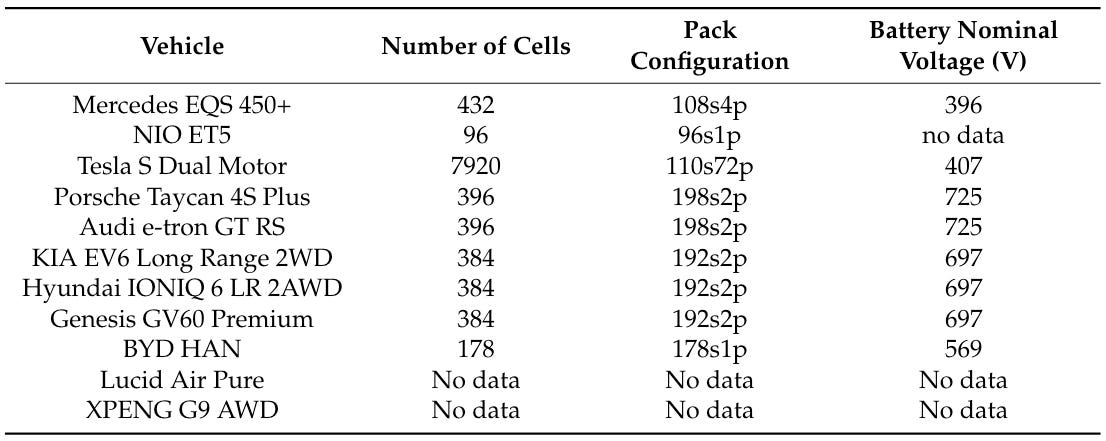
The table below shows the battery configurations for a variety of popular EVs in the market today. The battery pack configuration with X series cells and Y parallel cells is represented as XsYp.
The number of series cells is determined by the total voltage required by the battery system. It is just like stacking AA batteries in your flashlight to generate the required voltage. The number of parallel cells depends on the total current that must be supplied to support operation at a specified power level. Adding more parallel branches of series connected battery cells allows for greater current draw from the battery, and hence faster charging. The number of parallel battery banks needed also depends on the current capability of each individual Li-ion cell, and depends on its construction chemistry.
One of the primary functions of the BMS is to monitor the health and temperature of the Li-ion battery array which is key to maintaining the performance, lifespan and safety of the battery cells. It ensures that the cells in the battery are kept at uniform voltage levels and controls the thermal conditions of the battery array often using liquid cooling in hot conditions and electric heaters in winter.
Traction Inverter Design
The traction inverter converts DC voltage from the battery to AC voltage needed to drive the induction motor. While the actual inverter design can be quite complex, we will look at a basic implementation that provides a foundational understanding.
Two-Level Voltage Source Inverter (VSI)
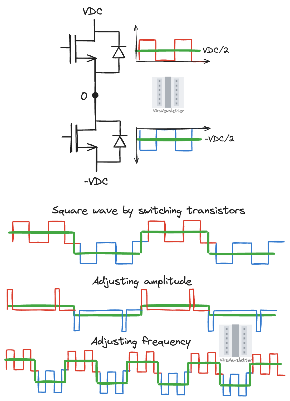
Let’s consider a single transistor that is switched between 0V and VDC with it spending 50% of the time in each state. In this 50% “duty-cycle” waveform, the average voltage in the switching period is VDC/2. Similarly, if the transistor is switched between 0V and -VDC, the average voltage is -VDC/2.
If we want to generate a square wave with a certain periodicity, we can switch transistors between positive and negative voltage rails alternately. The amplitude of the square wave can be adjusted by lowering or raising the duty cycle of the switching transistors. The frequency of the square wave is controlled by how often we switch between the upper and lower transistors.
We have converted a DC rail voltage into an AC voltage by switching transistors, but square waves are not a great choice. They are nonlinear, contain a lot of harmonic content and definitely not ideal to drive 3-phase motors. Sinusoidal waveforms are the preferred choice for driving AC induction motors.
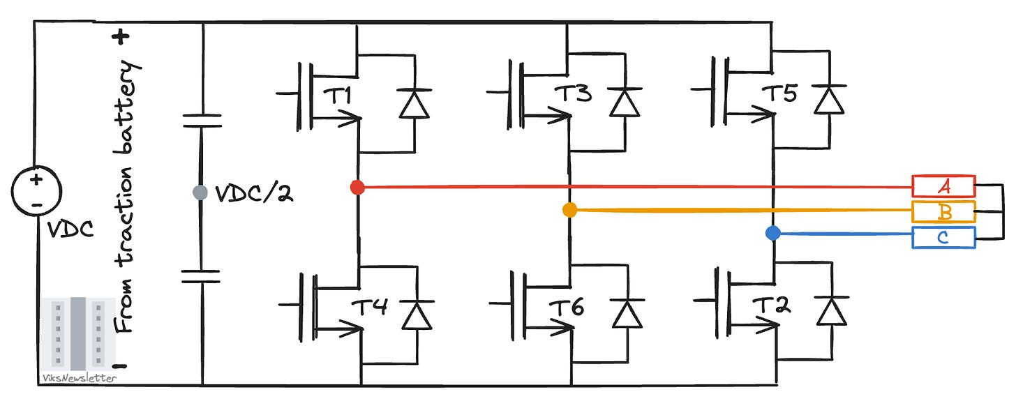
The square wave voltage idea can be used to generate a sinusoidal voltage and involves a voltage source inverter (VSI) circuit shown in the figure below. It has three parallel transistor branches, each to drive one phase of the 3-phase induction motor (represented by A, B, C). Each branch has two transistor devices that are operated as switches: a “high-side” switch connected to the positive power rail (T1, T3, T5) and a “low-side” switch connected to the negative power rail (T2, T4, T6). These switches operate in a complementary fashion, with special care to introduce “dead time” where both switches in a branch are not turned on simultaneously resulting in a shorting of power rails.
The diode connected across each switch is called a “free-wheeling or flyback” diode and provides a path to discharge the device after it is switched off, thereby preventing transistor damage from voltage spikes. The mid-point between the switches is connected to one of the phases of the AC induction motor. The capacitors between the power rails on the DC side is present to smooth out any ripples in the DC voltage from the traction battery, and is called the “DC link” capacitor.
Sinusoidal Pulse Width Modulation (SPWM)
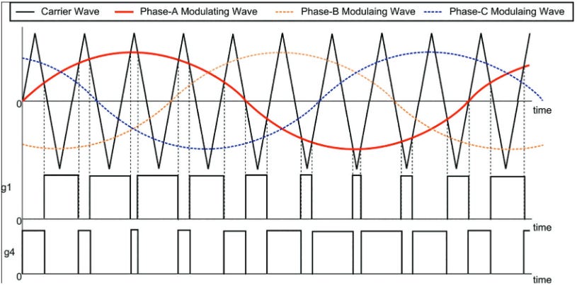
To generate a sinusoidal output from the inverter, a common method to switch these transistors involves using a sine-triangle pulse width modulation scheme. It involves the use of more waveforms to generate switching pulses:
A low frequency sinusoidal modulating waveform that resembles the desired output waveform (in colors below)
A high-frequency triangular waveform (in black).
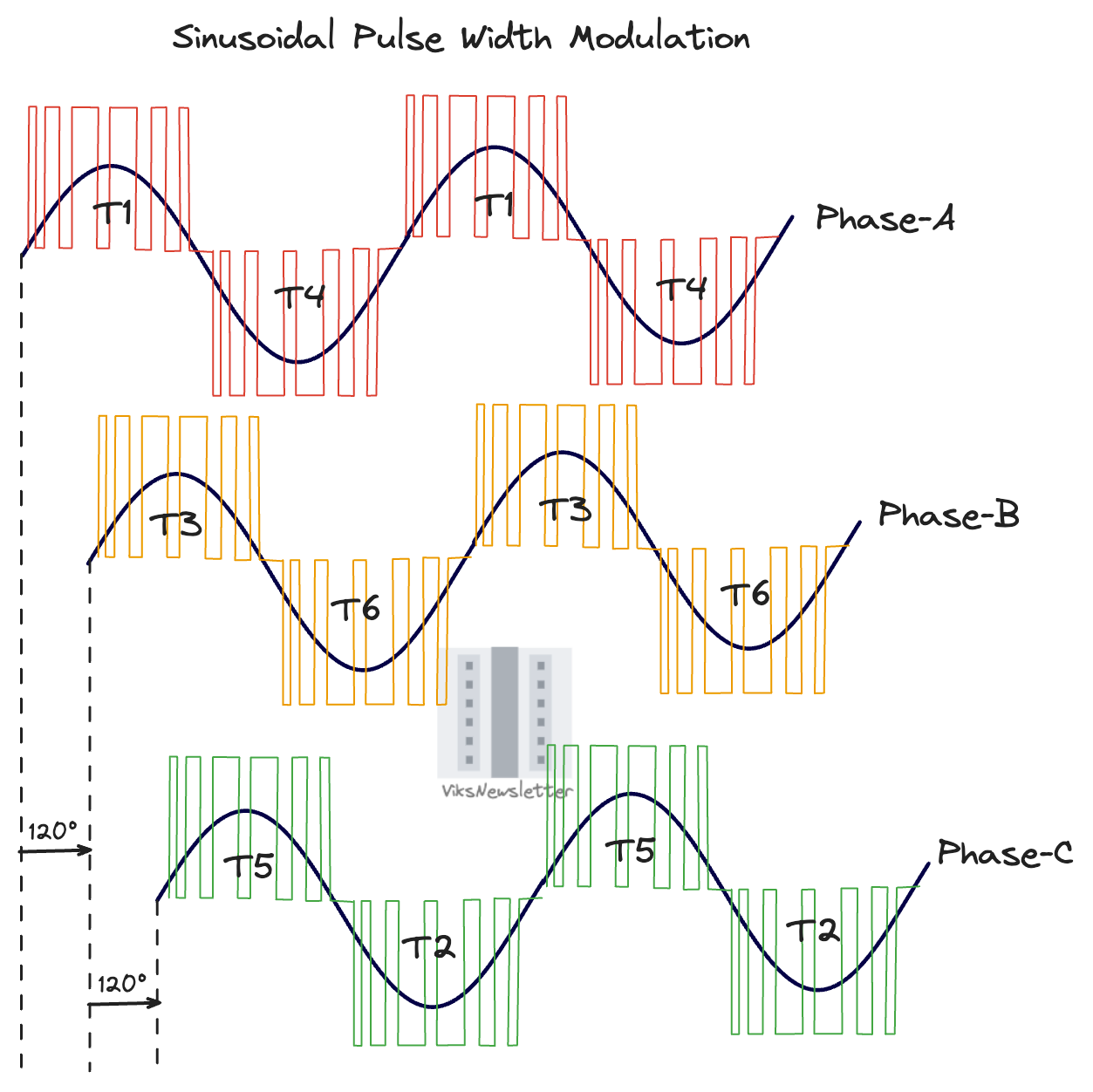
The modulating sinusoids are 120°apart for each phase and use the same principle of operation, so we will simply discuss what how it works for a single phase (phase-A in red). The other phases are generated by simply switching transistors in other parallel branches at time offsets.
The transistors are driven by a driver chip that has a comparator to determine which of the two voltage waves (sinusoidal or triangular) is higher at any instant and generates an output as,
If triangular wave > sinusoidal wave (black > red), turn on low-side switch
If sinusoidal wave > triangular wave (red > black), turn on high-side switch
The output signal is thus a train of pulses that are +VDC/2 when the high-side switch is turned on, and -VDC/2 when the low-side switch is turned on. Notice how the width of pulses are not the same anymore but instead vary with the magnitude of the sinusoid in the positive or negative half cycle. The average (or more technically, root-mean-square value) of these pulse trains approximate a sinusoidal AC voltage that is capable of driving a traction motor. Often there are lowpass filters at the output of these transistors to filter out harmonic content before being fed to the motor.
This mechanism to generate an averaged sinusoidal output signal from a DC voltage can control the speed and torque delivered by the motor to the wheels.
Speed: The frequency of the sinusoid controls the speed of the rotating magnetic field in the traction motor’s stator, and as a consequence controls the speed of the vehicle.
Torque: The magnitude of the sinusoid dictates how much current is driven through the motor, and when it intersects the stator’s rotating magnetic field, determines how much torque the motor produces. The magnitude of the generated sinusoid can be controlled by adjusting the duty cycle of the switching pulses.
One significant aspect we did not dive into here, is the nature of transistors used as switches. They have to handle the full voltage from the traction battery, which is often hundreds of volts, and have low switching losses to avoid dissipating power as heat. These transistors are built from special devices such as insulated gate bipolar transistors (IGBT) or wide bandgap materials like silicon carbide (SiC) or gallium nitride (GaN). This, however, is an in-depth topic for another time.
Further Learning Resources
In the video below, Prof. David Perreault from MIT provides an excellent academic explanation of how three-phase inverters work.
Edit: Michael Glidewell shared this amazing YouTube video with me on X that I thought I must share as part of this article.
A. Hren, M. Truntič, and F. Mihalič, “A Survey on the State-of-the-Art and Future Trends of Multilevel Inverters in BEVs,” Electronics, vol. 12, no. 13, p. 2993, Jul. 2023, doi: 10.3390/electronics12132993.
D. Chatterjee, C. Chakraborty, and S. Dalapati, “Pulse-width Modulation Techniques in Two-level Voltage Source Inverters – State of the Art and Future Perspectives,” Power Electronics and Drives, vol. 8, no. 1, pp. 335–367, Jan. 2023, doi: 10.2478/pead-2023-0023.
HEV/EV Traction Inverter Design Guide Using Isolated IGBT and SiC Gate Drivers
If you like this post, please click ❤️ on Substack and leave a comment. I’d love to hear from you and it reaffirms that I am not writing into the void.
Share this post with a friend, it really helps spread the word about this publication.
Join our Discord community and get in on the discussion!
The views, thoughts, and opinions expressed in this newsletter are solely mine; they do not reflect the views or positions of my employer or any entities I am affiliated with. The content provided is for informational purposes only and does not constitute professional or investment advice.


Very good explaination of sinusoidal wave and use for controlling torque and speed.
Thanks for this. I really enjoy my EV (a Chevrolet Bolt) and have wondered how the inverter worked.