How Automotive Radar uses Chirp Signals for Sensing
Understanding the engineering behind how your car can see, adapt and save your life.
Hey, I’m Vikram 👋!
Automotive radar has been of great interest to me, and I finally got a chance to dig into the basics of its inner workings. This field is a tasty mix of physics, RF engineering, signal processing and of late, machine learning and AI. The ability of your vehicle to “see” before you can, has substantial impact on the safety of our society. Thanks to Qi Wen for providing me with starting material to learn about mm-wave radar.
If you like this, please click ❤️ on Substack or share it with someone. This is an easy way to support this free publication.
Note: This article may be too long for email. Please view it directly on Substack by clicking on the title.
The field of radar is vast and has been around for decades, but in recent times there is a large market for automotive safety that makes this technology significant in the years to come. This article will serve as an introduction to how it works. I find the engineering behind pulsed and frequency modulated continuous wave (FMCW) radar for automotive applications fascinating. To the extent possible, without getting too technical, I’ll explore the topic over a series of articles. I hope you will join me.
In this article, we will cover:
Differences between pulsed and continuous-wave radar
Doppler effect and frequency modulation for distance measurements
Design of frequency chirps for pulsed and FMCW radar
Trade-offs in choosing the correct chirp signals
Read time: 12 mins
Need for Automotive Safety
According to the 2023 WHO report, there are over a million worldwide road traffic fatalities every year, with the highest fatalities occurring in the southeast asian region (28% of global). It remains the leading cause of death for children and people under 30, and worldwide initiatives have been taken to improve road safety. For example, Vision Zero is a project initiated in the 1990s whose focus is on achieving zero traffic fatalities and injuries through technology, policy, and design.
Today, the rise of electronics in automobiles has enabled safety features that allow the driver to actively avoid fatal mistakes increasing both driver and pedestrian safety. Reports place the total market for automotive safety systems at over 200 billion by 2030 with an annual growth rate of 9%.
Among these safety features are adaptive cruise control, blind spot detection, rear collision warning, lane departure warning, lane keep assist, and automatic emergency braking and steering. Advanced Driver-Assistance Systems (ADAS) are designed to help implement these technology features in automobiles.
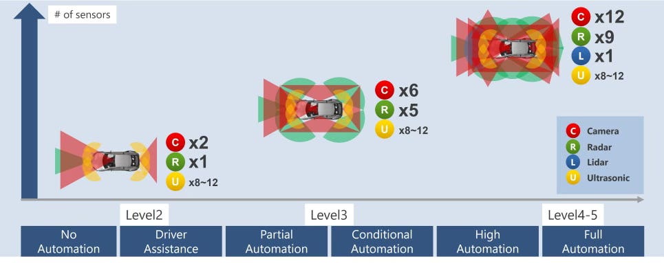
An essential element of ADAS systems is radar, which stands for radio detection and ranging. Radar has been around for a good part of a century, but its use for automotive safety has been more recent. For example, the 5th generation Waymo Driver has 6 radar sensors, along with a variety of ultrasonic, camera and lidar sensors.
Automotive radar uses both pulsed and frequency modulated continuous wave (FMCW) radar. We will explore how these things work.
Pulsed versus Continuous-wave Radar
There are two approaches to radar detection worth discussing:
Pulsed Radar: A short burst of RF energy for a known time duration is transmitted. The signal travels to an object, bounces off it, and hits the receiver. The distance to the object is calculated from the round trip delay.
Continuous-wave (CW) Radar: In this radar, there is no distinct start and stop times to the RF energy. The signal is continuously transmitted and received at all times. Since there are no defined transmission intervals, round trip delay measurement is not possible. Thus, special methods are used to estimate distance as we will see shortly.
The downsides of pulsed radar are:
The burst of RF energy needs to be sufficiently high powered so that the reflected signal reaches the receiver with good fidelity. This makes the design of transmit amplifiers expensive and challenging.
It is difficult to measure short ranges because the pulse duration needs to be extremely short. It is better suited to long range applications.
The time taken to switch from transmit to receive mode presents a 'blind spot' where no radar tracking is available.
Pulsed radar does have its use cases when long range, high speed target tracking is needed, particularly for military applications. It is also useful when fine resolution is need between radar targets.
On the other hand, CW radar can utilize lower power transmit signals which makes the design of radio electronics much easier and economical for automotive safety applications. CW radar can be designed to have short, medium or long range capability depending on system design and since the RF signal is always on, it does not have blind spots.
Measuring Velocity with the Doppler Effect
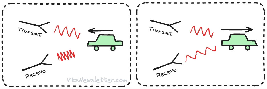
Doppler effect is a phenomenon where the frequency of a signal source shifts depending on whether it is moving towards or away from an observer. Think of the sound of an approaching and receding train horn. When the signal source is moving towards the observer, the frequency shifts to higher values, and vice versa.
The velocity of an object can be measured from doppler shift of the RF frequency in both pulsed and CW radar. The doppler frequency shift due to an object moving at 100-200 mph is in the range of kilohertz for an RF signal in the 77-81 GHz range, a licensed frequency band for automotive radar. The detection of this shift is done by multiplying the received signal and the transmitted signal in a mixer, resulting in sum and difference frequencies. The sum frequency will be over 150 GHz and is easily filtered out by a low-pass filter that only allows the difference frequency (or beat frequency) in the kilohertz range through.1 The greater the speed of the object, the greater this beat frequency. Thus, by measuring the beat frequency, the velocity of the object can be estimated.
Measuring Distance with Frequency Modulation
Round trip delay measurement is possible using a fixed frequency pulsed radar to estimate distance, but the use of frequency modulation provides advantages in detection. CW radar relies on doppler effect, beat frequencies and frequency modulation to estimate distance. We will look at both next.
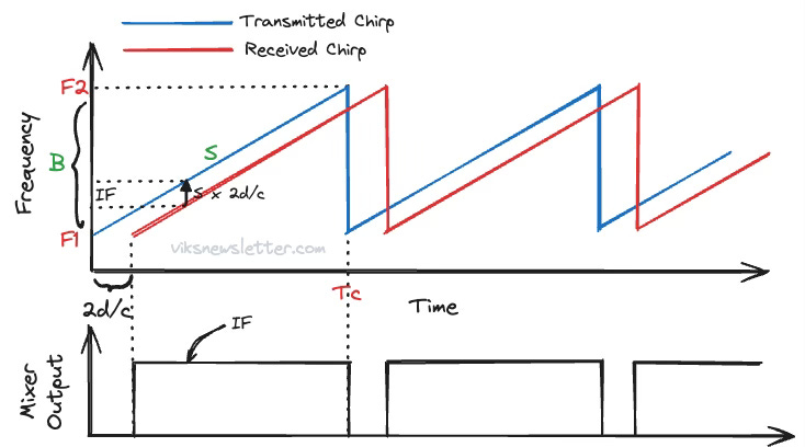
In both pulsed and CW radar, the RF signal used linearly increases in frequency from one value to another in a fixed time period. It is often called a chirp, whose frequency-time plot is shown below. The linearly frequency modulated RF signal goes from a starting frequency F1 to an ending frequency F2 during the chirp duration Tc. The bandwidth of the chirp B (=F2-F1), and the frequency slope S (=B/Tc) are critical system parameters.
But why go through the trouble of generating such a signal?
Pulsed Radar Chirps
To understand why in the context of pulsed radar, we need to understand the concept of a matched filter. A matched filter is a signal processing step used to extract a known signal from a noisy signal, like the one received by radar. The way this works is to find out how correlated the received signal is, to a known waveform known as a template signal. This is done by convolving these two signals together.
Let’s assume the transmitter sends out a RF pulse at a fixed frequency for a duration Tc. It is reflected from a target and received along with noise. The received signal is convolved with a constant frequency pulse as template signal. As long as the pulse does not overlap the template, the correlation is zero. As the pulse starts to overlap, there is some correlation, and it reaches a maximum when it is completely aligned.
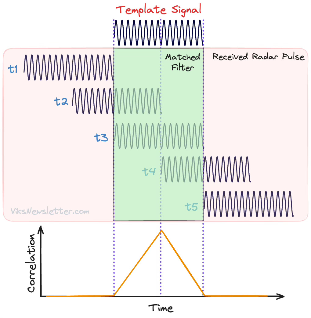
The peak of the matched filter output tells us the delay between the transmitted and received waveforms and is useful for calculating the distance of the target object. Using a constant frequency pulse has two problems:
Signal-to-Noise Ratio (SNR): As the noise level rises, it quickly becomes difficult to tell where the peak is. We could increase the power level of the transmitted pulse, but it makes it hard to design linear transmit amplifiers that work well.
Resolution: If there are reflections from two targets, the received pulses might overlap making it difficult to detect any peaks. To improve resolution and distinguish between objects, we could make the pulses shorter to minimize the overlap between signals. But shorter pulses are harder to distinguish from noise. There is always a trade-off between resolution and SNR.
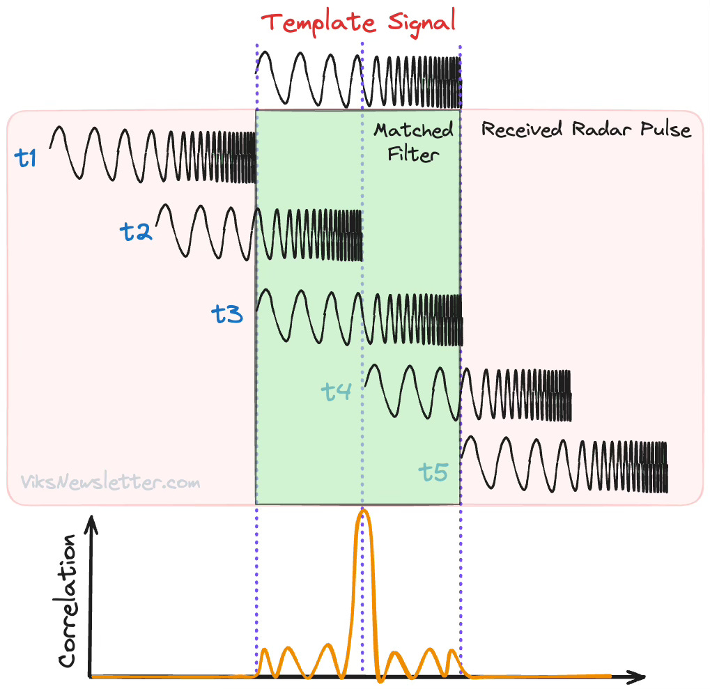
The ability to resolve targets in the presence of noise dramatically improves when a chirp is used. When an RF signal with continuously increasing frequency is used, the output of the matched filter produces sharper peaks. To understand how, let's look at the correlations of a received chirp with its corresponding template signal.
As before, when the two signals do not overlap, the correlation is zero. When they start to overlap, the correlation is still low because the waveforms do not line up when they are of different frequencies. The correlation is maximum only when the two FMCW signals exactly line up.
This results in a more distinct peak that is easy to identify even in the presence of noise. The output of the matched filter is squished in time, and therefore the technique is called pulse compression. Due to the narrow peak in the detected signal, two reflected chirps that overlap in time can still be detected. This was not possible with a constant frequency signal.
In fact, the ability to distinguish between two closely spaced signals in time no longer depends on the width of the pulse. Instead, it depends on how much the frequency changes within the pulse, or the bandwidth of the signal. Increasing signal bandwidth gives better resolution without increasing the power of the pulse. In the next section, we will exactly calculate range resolution for a specified bandwidth.
In summary, the use of a chirp signal results in distinct peaks after matched filtering that are much more easier to detect compared to constant frequency signals.
If you want to understand this idea in greater detail, then check out this video.
Frequency Modulated Continuous Wave (FMCW) Radar
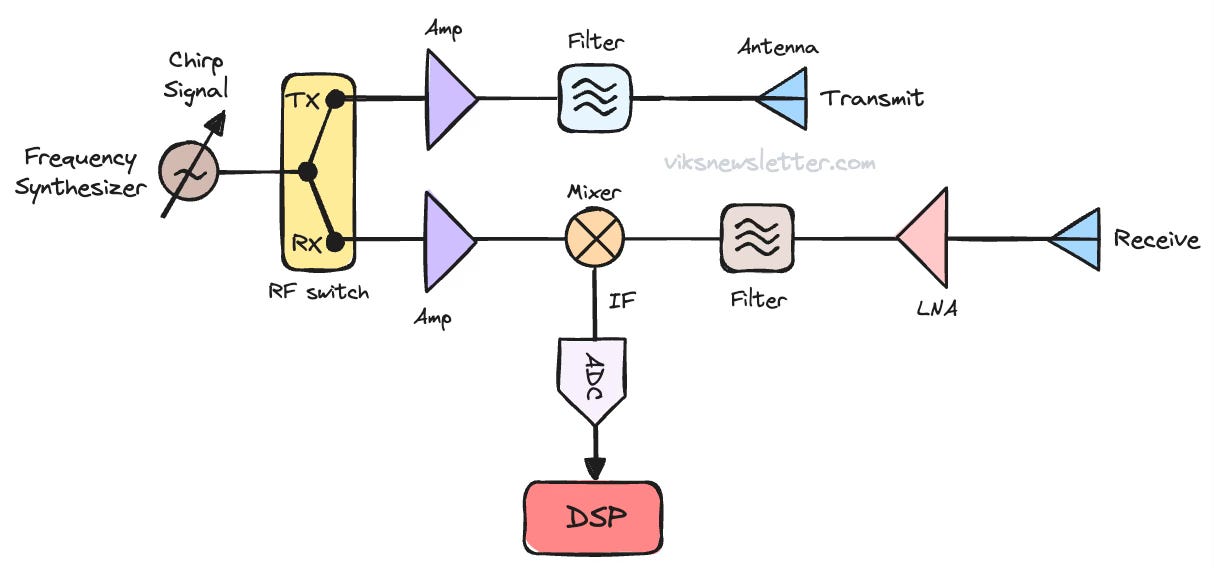
The block diagram of a FMCW radar system is shown below. A frequency synthesizer generates a series of chirps that resembles a saw tooth waveform in frequency-time plot, that is amplified and sent out via the transmit antenna. The signal travels through the air, bounces off the object and is received by the RX antenna. The received signal is mixed with the original synthesized signal to generate an intermediate frequency (IF), much like in a superheterodyne receiver. It is then digitized and sent to the digital signal processing system.
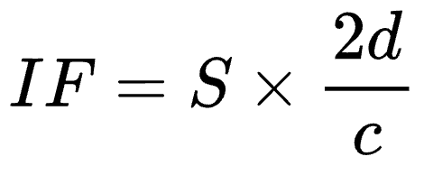
If the target is stationary, then the received signal is a chirp delayed in time. The delay in the signal is the time taken by the signal to travel to the object located at a distance d, and back, divided by the speed of light. The mixing operation results in an intermediate frequency that is proportional to the distance of the object. If S is the frequency slope of the chirp signal, the IF is calculated as
The IF signal is digitized by the analog-to-digital converter (ADC) only in the time window where both transmitted and received chirps are present. In practice, the delay between transmitted and received chirps is quite small, usually under 5% of the total chirp period. So both chirps are available for over 95% of the sensing period to generate an IF.
Range Resolution
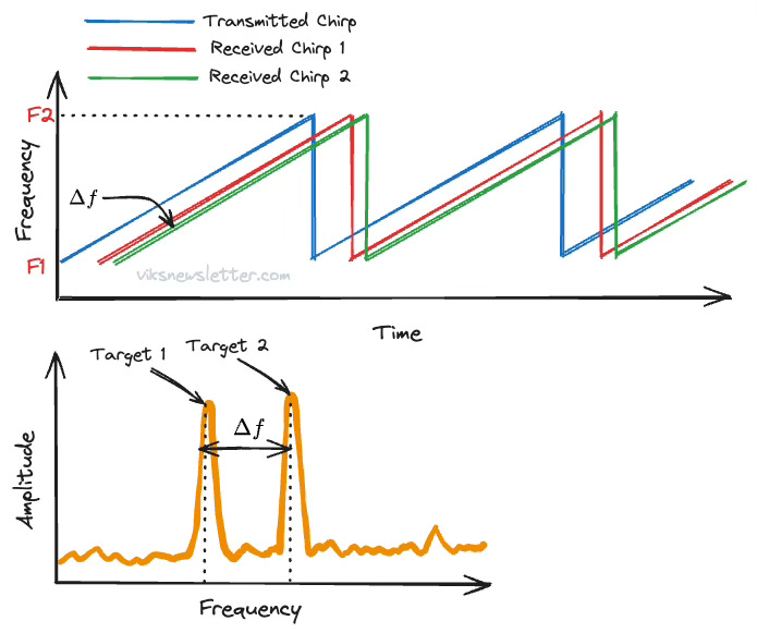
If there are multiple targets in the radar sensing field, then multiple reflected chirps will be received by the radar, which will produce multiple IF.
The ability to resolve two nearby objects is called the range resolution of a radar.
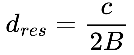
The ability to distinguish between peaks in the IF spectrum depends on the duration of the chirp signal Tc. A higher time-window allows for better resolution of closely spaced objects. For the same frequency slope S, this means a higher frequency sweep bandwidth B. Two IF signals spaced Δf apart can distinguished if Δf > 1/Tc. Using our earlier relationship mapping IF to distance, the range resolution of a radar is given by
To improve resolution of two nearby objects, a higher frequency bandwidth is needed for the chirp signal. An RF chirp from 77GHz - 81 GHz (B=4GHz) translates to a range resolution of 3.75 cm.
Maximum Range
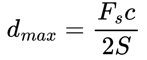
How far an object can be and still be sensed by the radar depends mainly on the ADC bandwidth available to digitize the IF signal. For a far away object, the IF signal frequency will be higher and the ADC bandwidth should be sufficiently large to handle that. For an ADC sample rate Fs, the maximum range of the radar is given by
This tells us that for a given ADC sampling rate, the maximum range can be improved by lowering the frequency slope of the chirp.
Choosing the right Chirp signals
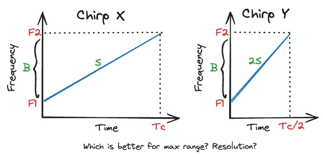
Consider two chirp signals with the same frequency sweep bandwidth B. Chirp X has a longer chirp duration, but lower frequency slope. Chirp Y has a shorter chirp duration but higher frequency slope.
Both chirps give the same range resolution because they have the same bandwidth. However, because chirp X has a lower slope, it generates lower IF frequencies. This means that the ADC bandwidth requirements are more relaxed for chirp X and therefore is capable of sensing greater distances. While chirp Y is capable of faster sensing due to smaller chirp duration, it places a higher specification on ADC performance and corresponding limitations in maximum range.
There is a lot more to automotive radar we can talk about in future articles. Please make sure you subscribe if you haven’t and leave me a comment with your thoughts.
Due to the image problem we discussed earlier in the context of radio receivers, the beat frequency is the same whether the received signal is above or below the transmitted signal. Hence, we cannot tell if the object is moving toward or away from the receiver. To resolve this we need another transmitted signal offset by 90 degrees in phase to generate in-phase and quadrature (IQ) components, mix them both down and examine their phase components. Just know that for now, and we'll maybe get into this at another time.
The views, thoughts, and opinions expressed in this newsletter are solely mine; they do not reflect the views or positions of my employer or any entities I am affiliated with. The content provided is for informational purposes only and does not constitute professional or investment advice.



You can also discover the power of Linear Frequency Modulation (LFM) from my recent article https://wirelesspi.com/the-power-of-pulse-compression/
There are real receiver architectures being used now in automotive radar mmics as well. However I wonder without phase information how targets are identified if they're moving towards or away? Just Doppler analysis? Could you please elaborate the differences between IQ and real receivers?