How Automotive Radar Measures the Velocity of Objects
How to design the perfect chirp signal for distance and velocity measurement.
Hey, I’m Vikram 👋!
In this article, we continue the discussion on automotive radar and how it is used for distance and velocity measurements. We get a bit technical in this article, but I’m hoping enough pictures will get the point across. If anything is unclear, leave a comment on Substack and I’ll try to help.
If you like the content, please click ❤️ on Substack and subscribe! Sharing the article on social media is a great way of supporting this publication.
Note: This article may be truncated in email. Please view it directly on Substack by clicking on the title.
In the previous article on automotive radar, we focused on the applications of pulsed and frequency modulated continuous wave (FMCW) radar and their basic operating principles for distance measurements. We only briefly touched on the idea of using doppler shift to measure velocity. In this article, we go deeper into how velocity is measured using FMCW radar. If you haven’t read the last article on this topic, I’d highly recommend you check out the link below. It covers a bunch of the basics.
In this article, we will cover:
The ambiguity in simultaneous range and velocity measurement
Polar visualization of a radar chirp
Using phase for velocity estimation
Concept of a Doppler FFT and range-doppler plots
Practical examples of chirp waveforms
Read time: 10 mins
The Ambiguity Problem
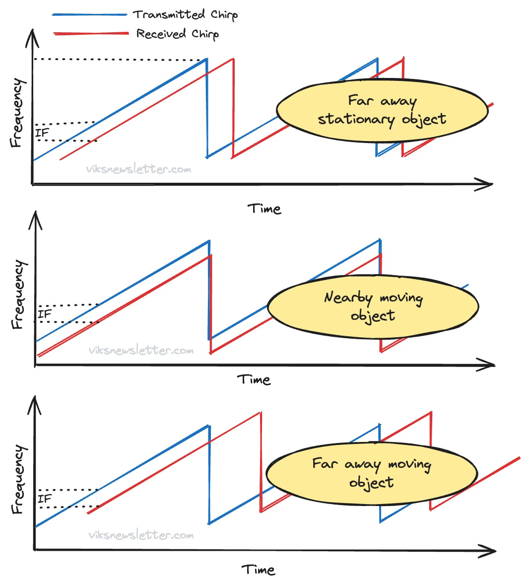
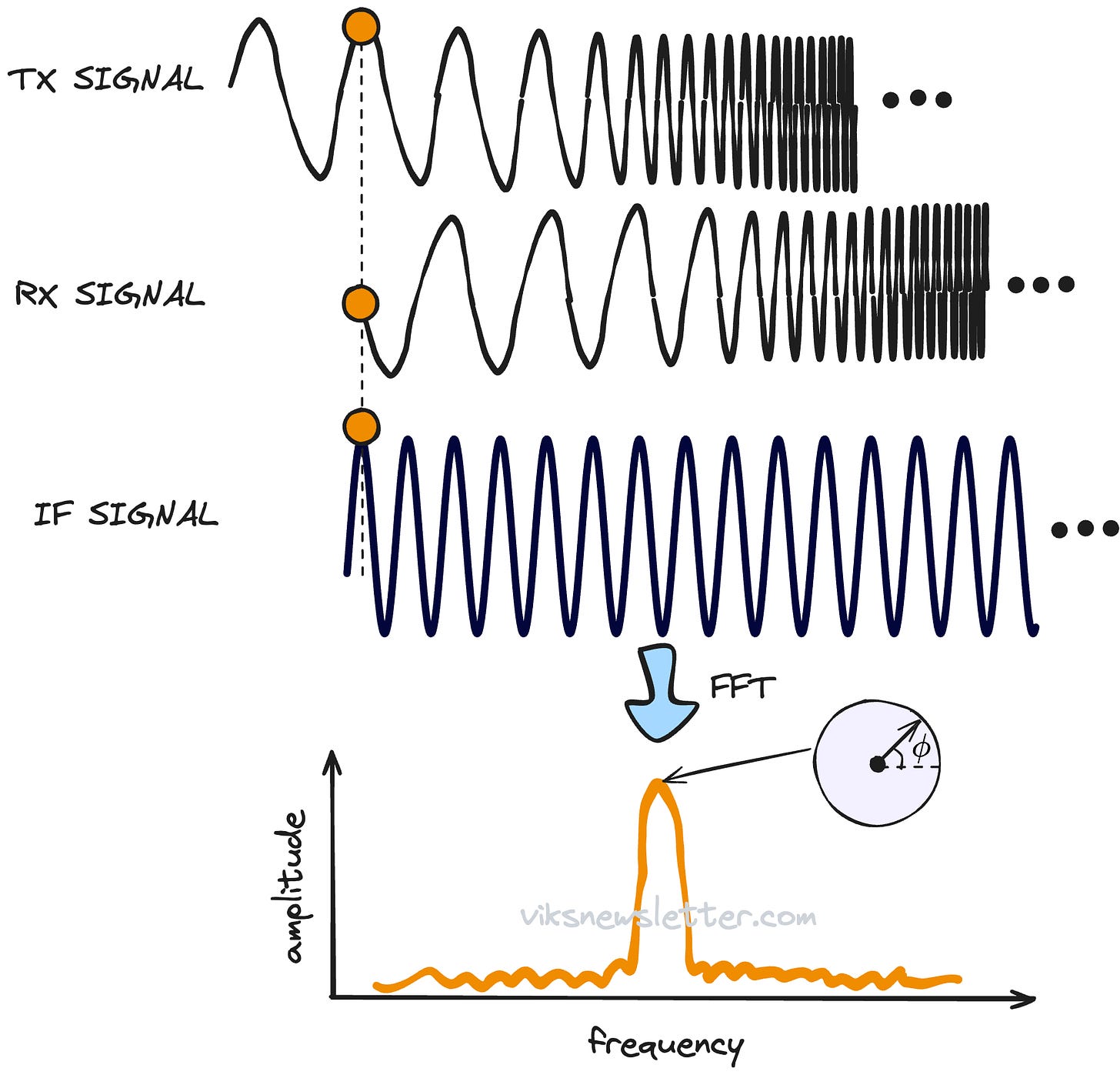
Earlier we looked at how frequency modulated chirp signals are used in FMCW radar systems. The transmitted chirp reflects off a target and is received after a time delay. Since the chirp signal has a continuously increasing frequency within the chirp period, there is always an instantaneous frequency difference between the transmitted and received chirps.
These chirps are multiplied together in a mixer to generate a beat frequency, which is digitized by the ADC and processed in the digital domain. This beat frequency is proportional to the distance to the object.
The velocity of the target also manifests as a frequency shift in the received chirp due to Doppler effect. The simultaneous measurement of range and velocity results in an IF signal whose value cannot be solely attributed to range or velocity. The figure below shows the same IF frequency generated in various scenarios of stationary and moving objects. Simply performing range and velocity estimations from IF signal is inherently ambigous.
In addition, we mentioned in passing in the last article that it is difficult to tell if an object is moving towards or away from the radar because received frequencies both above and below the transmitted signal frequency mixes down to the same IF (the image problem.)
Several astute readers pointed out that phase information can be used to further resolve target range and velocity. This is what we will discuss in this article.
An Upgraded Perspective of a FMCW Chirp
To better understand how phase plays a role, we need to upgrade our visualization of the time-domain representation of an FMCW chirp - from two to three dimensions. A sinusoid when represented as a complex signal, is a helix spiraling forward in time.
To extend this idea to frequency modulated waves, we'll use an analogy.
Visualize a spring. A complex sinusoid at any given time is a point along the spring. As time passes, the point spirals forward along the spring. In an earlier article, we visualized this when understanding the need for negative frequencies. Give it a quick look over if you need a better mental picture.
If you look through the axis of the spring, you will see a circle. As the signal propagates, the value at any instant is given by an amplitude that corresponds to the radius of the circle, and an angle that changes with time. This is the complex polar representation of a sinusoid.
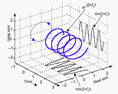
For an FMCW signal in complex form, visualize the same spring but more compressed on one end, and elongated at the other. This represents a complex signal whose frequency is continuously increasing, like in a radar chirp. Looking through the spring again, we will have a dot that traces a circle with a magnitude and phase as the wave propagates. The difference now is that it will spin faster around a circle as the frequency is linearly increased.
The main takeaway here is that both constant frequency and FM signals can be represented in polar form, with magnitude and angle.
Velocity Measurement from Phase
The multiplicative mixing process between transmitted and received chirps not only results in a constant1 beat difference frequency, but it also does something to phase. The IF signal has a phase that is the difference between transmit and received signal phases.
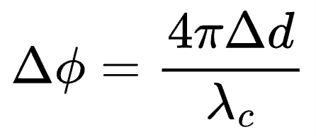
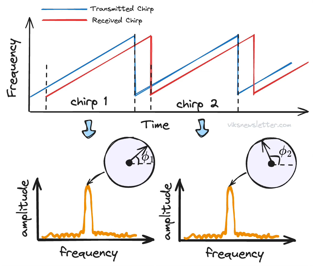
When the IF signal is represented as a peak in the spectrum, we are only looking at half the story - the magnitude of the signal. The peak also has a phase value that is equal to the initial phase of the IF signal. So how does phase change with the distance to the object? This is fairly simple to calculate if the round trip delay changes by Δt=2Δd/c, and the instantaneous wavelength is 𝜆c.
So the movement of an object produces an IF shift of S⨉2Δd/c (as we calculated in the last newsletter), and a phase change Δϕ, both of which are directly proportional to the change in distance. Which measurement is more sensitive?
For a 77 GHz radar with 4 GHz bandwidth and 40 microsecond chirp time, the IF shift would be about 660 Hz, while the phase shift would be about 180 degrees. 660 Hz would be indistinguishable in the fast Fourier transform (FFT) spectrum2 unless a very long observation window is used. Phase measurement is much more sensitive to small changes in range, and easily detectable.
The phase sensitivity is useful for other applications such as vibration detection and remote vital sign monitoring because small changes in distance produce easily measurable shifts in phase.
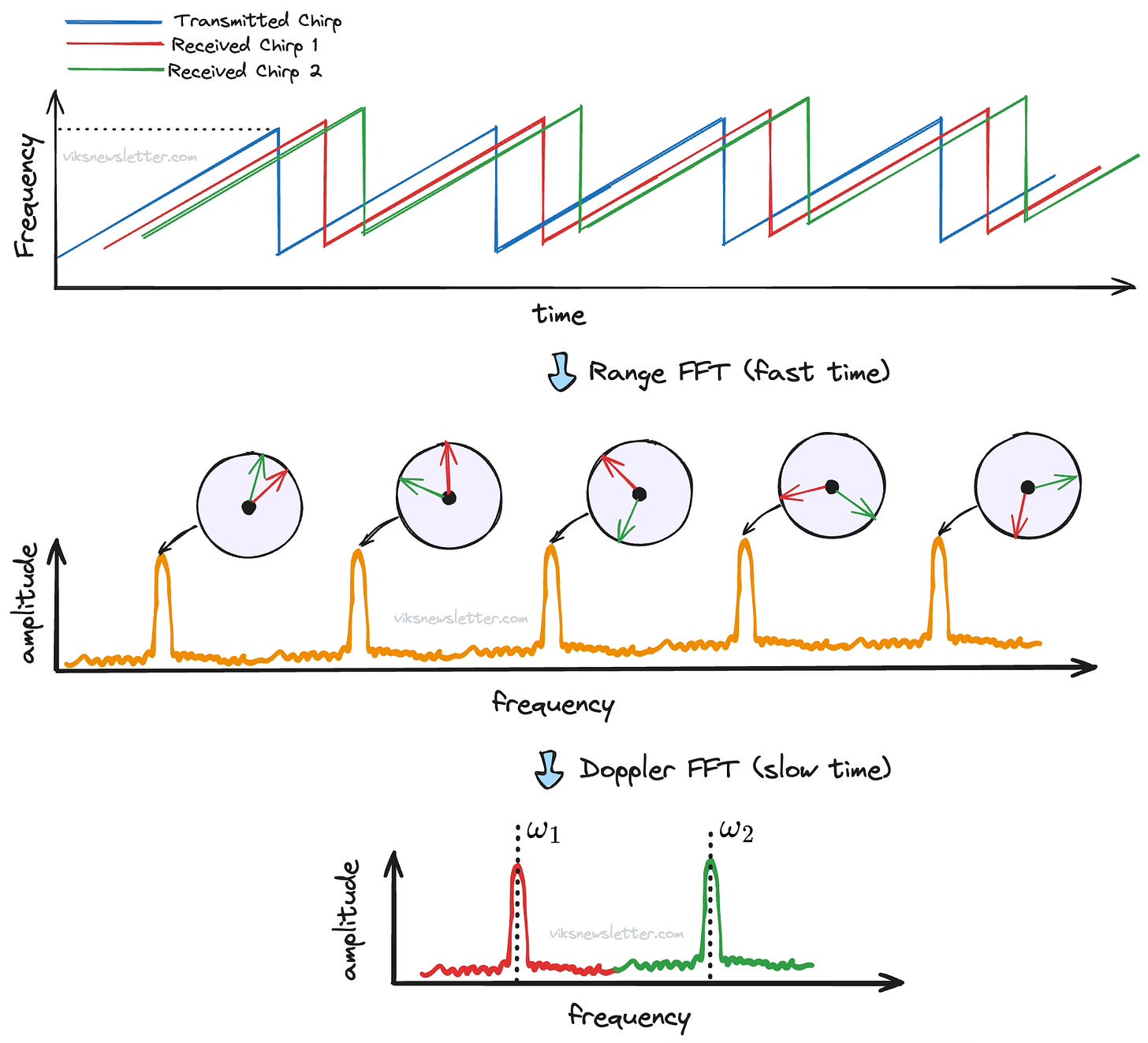
This sensitive phase shift can be used to estimate velocity of the object by estimating how much the phase changes in a given interval of time. To do this, two chirps are emitted spaced apart by chirp time Tc. Computing FFT on the IF signal (called Range FFT) would result in two peaks in the spectrum whose frequency values are closely spaced (or the same) but with differing initial phases.
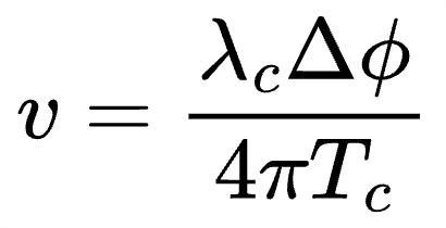
If the object velocity is v, then it would have moved a distance of v times Tc. Using vTc instead of Δd in the phase equation above would allow us to calculate velocity as
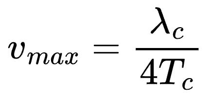
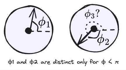
But what is the maximum velocity that can be measured using multiple chirps? The measurement of phase is unambiguous only if the phase change is lesser than π radians (see picture below), because it is hard to differentiate between clockwise and anti-clockwise phase rotations for Δϕ > π. By setting Δϕ = π, we get maximum velocity as
This means that using faster chirps (lower Tc) will help resolve faster velocities, but as we saw in an earlier newsletter, will restrict the maximum distance that the radar can sense. There is a direct trade-off between maximum distance vs maximum velocity measurements, and selection of proper chirp parameters are essential in classifying radar as short, medium or long range. We will look at practical examples later.
Doppler FFT for Velocity Estimation
So far we have looked at velocity measurement of a single radar target. What if there are multiple objects moving at different velocities? As long as they are at different distances, they will result in different IF frequencies, and distinct FFT peaks each with phase change information that can be used to calculate velocity.
The problem arises when multiple objects are in the same range, but moving at different velocities. In this case, the FFT peaks will overlap, and even if phase change information is available, it is hard to tell which phase change corresponds to which object.
The general solution to this problem is to use a sequence of N-chirps in succession, called a frame. This is the fundamental unit of transmission in FMCW radar. The time between two consecutive chirps is called the pulse repetition rate (PRT), and plays a key role in the accuracy of doppler velocity estimation.
Computing the range FFT of each chirp gives a series of peaks whose frequency is the almost constant (if the range is the same) but each containing different phase information. Computing the range FFT is said to be done along the fast-time axis, since many samples are being collected for each chirp. An object moving faster will accumulate more phase shift over the sequence of N chirps compared to a slower moving object.
To calculate velocity of the object, we need to compute FFT over multiple chirps. The idea behind this is to find out how much the phase has changed between different chirps. The rate of phase change along with the direction of phase change will tell us how fast the object is moving, and whether it is moving towards, or away from the radar. The resulting FFT will provide two peaks in the spectrum, corresponding to the velocity of each object.
Also, because the sampling rate between chirps will depend on the pulse repetition rate, it will be slower than the range FFT calculation which is done on every chirp. As a result, such an FFT is said to be done along the slow-time axis.
An FFT computed over a sequence of range FFTs corresponding to N chirps in a frame is called a Doppler FFT.
The resulting FFT can be plotted on what is called a range-doppler FFT, which can immediately identify how many targets are present, what their ranges are and how fast they are moving in what direction (towards or away).
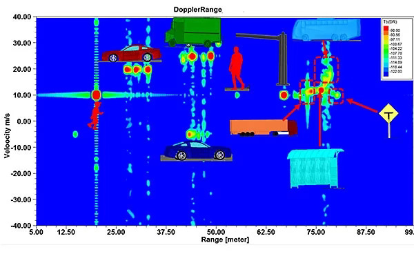
Immediately we are faced with the question of resolution: How close can the two velocities be, so that the peaks will be uniquely identifiable?
In a frame with N-chirps, two angular frequencies will be distinguishable if their difference is greater than 2π/N. Setting Δϕ=2π/N in the velocity equation gives us the expression for minimum resolvable velocity.
where Tf=NTc is the total frame time. This means using a longer observation window with more chirps will help resolve velocity better.
Practical Examples of Chirp Design
Designing a chirp for a given application comes down to three factors, and their trade-offs which are summarized below.
Bandwidth of the chirp: The higher the frequency bandwidth, the better the distance resolution.
Duration of the chirp: Short, fast chirps for a given bandwidth, allow higher velocity measurements but limit maximum range of measurement, and vice versa.
Number of chirp repetitions in a frame: Greater number of chirps increase total frame length, but allows for increased velocity resolution.
Typical chirp parameters for various automotive radar applications are shown below for a Texas Instruments mm-Wave radar chip for Long Range Radar (LRR=225m), Medium Range Radar (MRR=125m), Short Range Radar (SRR=45m) and Ultra Short Range Radar (USRR=22m).
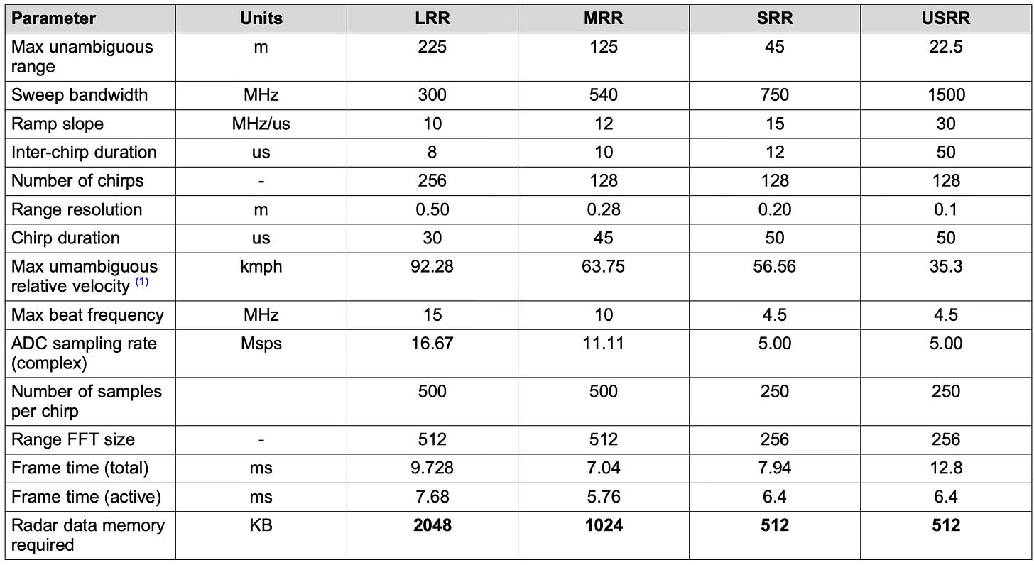
Looking at this table closely helps us understand how the choice of chirp parameters affects what the radar system is capable of doing, and puts into practical terms all the trade-offs we have discussed in the last article and this one, regarding range and velocity measurement.
The table below shows another application where a mm-Wave radar system is used as a proximity sensor for ground-clearance measurement or door/trunk opener. This low-cost chip (AWR1443 from Texas Instruments) allows the use of high-performance radar for short range detection in lieu of ultrasonic systems.
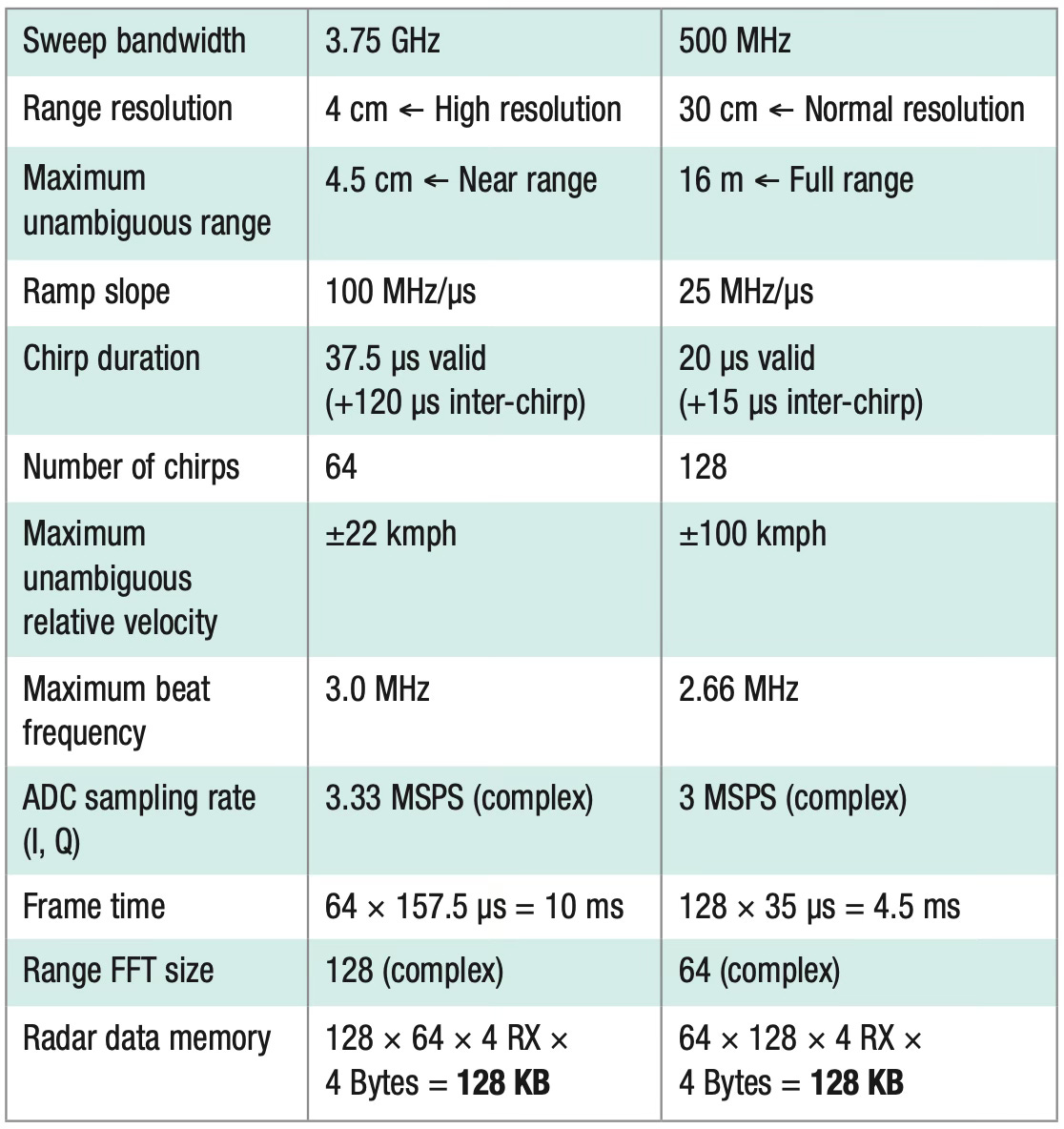
One important aspect of designing a system to support a given radar chirp frame is memory. Remember that the computation of doppler FFT can only occur when all the range FFTs are computed. Hence, the system should have sufficient on-board memory to store the radar data before the 2-dimensional range-doppler plot can be generated.
Many radar chips include a radar hardware accelerator that offloads frequently used computations away from the CPU, and is primarily geared towards fast FFT computations. There is a dedicated DSP processor that performs all the necessary data processing for radar calculations.
In addition, there are other considerations such as idle time between consecutive chirps to allow the frequency synthesizer to ramp down from the highest to the lowest frequency.
We have discussed distance and velocity measurements using FMCW radar. In the next article, we will look at angle estimations and other related topics.
See you next week!
The views, thoughts, and opinions expressed in this newsletter are solely mine; they do not reflect the views or positions of my employer or any entities I am affiliated with. The content provided is for informational purposes only and does not constitute professional or investment advice.
not frequency modulated because both transmitted and received chirps have the same slope, and their difference results in a constant frequency.
used to convert time domain signals to frequency domain.




How could we generate an image of the object in sight using radar(As it was shown).
A single chirp signal would be giving an information about a single point in space from where it is reflected, how do we map full object.