How does a Phased Array Antenna work? Types of Beamforming Architectures
How antenna beams are electronically steered, pros and cons of different phased array architectures, and Starlink's Dishy McFlatface 📡.
Hey, I’m Vikram 👋 and thanks for reading!
I’d really appreciate if you reply to this email and let me know what topics you’d like to see or what challenges you are facing. The feedback will help me improve the content quality and tailor it to what readers want. Even a few sentences will do! 📝
You can also reach me on LinkedIn/X or join the community on the Substack chat.
If you like these articles, please let others know. Word of mouth helps grow this newsletter! 🙏
In a previous article, we discussed how arraying antennas causes the radiated pattern to narrow due to wave interference. In this article, we will build on that concept to understand how to steer the narrow beam using phase shifts.
You will learn:
how radiated beams are electronically steered
different phased array architectures, their advantages and disadvantages
about Dishy McFlatface
If you don't know who that is, read on!
Why Steer Antenna Beams?
A narrow radiation beam from an array, as opposed to an omnidirectional antenna, cannot transmit and receive in all directions. To maximize signal reception, we need to point the antenna in the direction of the source. Historically, motorized platforms were used to manually rotate the antenna to do so.
For many applications, such methods are heavy, cumbersome, and slow. Furthermore, mechanical wear and tear make it unreliable. In modern communications, the antenna beam must be steered in milliseconds to a different direction.
The use of phased array antennas offers a solution for rapidly steering beams using electronic control. The basic operating principle is that you can steer the beam in any direction by precisely feeding each antenna in the array with a progressively delayed version of the signal (or a phase shift). Let's see how this works.
Applying Phase Shifts to Antennas
In the article on antenna arrays, we looked at how constructive interference sharpens the radiated beam when two antennas spaced half a wavelength apart are fed with signals of equal amplitude and phase.
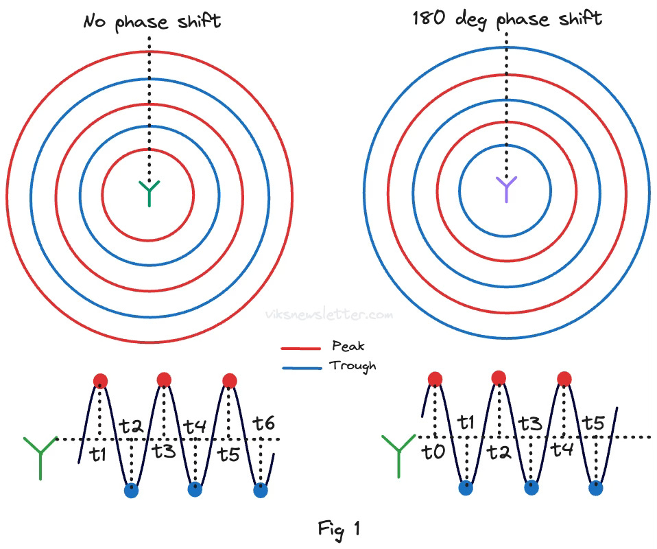
What happens if the phase of the signal fed to one of the antennas is shifted (by delaying it) compared to the other one? Figure 1 shows two radiated patterns from an omnidirectional antenna; one with no phase shift and the other with a 180 degree phase shift. The wave peaks emitted by one antenna coincides with the troughs of the phase shifted antenna at any point in time.
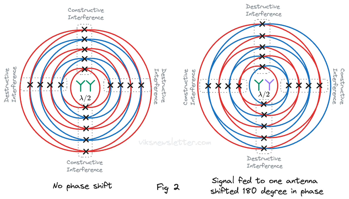
Figure 2 shows the resulting interference pattern when two antennas are placed half a wavelength apart. On the left figure, the signals fed are of the same phase. On the right, they are shifted by 180 degrees.
When there are no phase shifts present, constructive interference in the top and bottom results in the energy being more directed in that direction while destructive interference to the left and right sides produce nulls. Such an array is called a broadside antenna array.
With 180 degree phase shift between the two antennas, constructive interference occurs to the side instead, while destructive interference produces nulls in the top and bottom. Such an array is called an endfire antenna array.
We were able to steer the beam from vertical to horizontal by simply changing the phase of the signals fed to the antenna. We converted a broadside antenna into an endfire antenna.
Using a phase shift that is between 0 and 180 degrees causes the antenna beam to point somewhere between broadside and endfire directions. In practice, to avoid distortions in the radiated beam, the antenna beam is only steered on either side of the broadside direction, never all the way to endfire.
Multi-Antenna Arrays
In both of these cases, the beam can be made narrower using more antenna elements in the array. But what phase shifts should be provided to each antenna element in the array? Let's look at this closely.
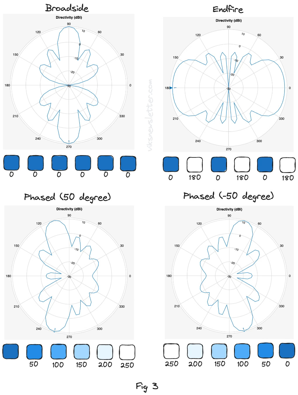
Figure 3 shows a 6-element linear antenna array. The squares represent radiating antenna elements color coded to show various phase shifts to the applied signal. Depending on the phase shift applied to each antenna, the following radiation patterns can be achieved.
Broadside: Each element in the array is fed with a signal with same amplitude and phase. The resulting radiation pattern has its maximum radiation in the +/- 90 degree direction in the azimuth plane.
Endfire: Each alternate antenna is fed with either 0 degree or 180 degree phase shift. The resulting radiation pattern has its peaks in the 0 and 180 degree directions in the azimuth plane.
Phased: Each consecutive element in the array is fed with a progressive delay of +50 or -50 degrees. The main beam can be steered on either side of the broadside direction. Increasing the phase shift to each antenna element will further steer the beam away from the broadside direction.
To steer a beam in both around in azimuth and up and down in elevation, we need to phase shift the signal to all antenna elements in a two dimensional planar array. Depending on the phase shift applied to each linear dimension of the 2-D antenna array, the beam can be made to point to any desired direction.
Phase Shifting Architectures
In theory, it is easy to see that the antenna element requires a phase-shifted version of the signal to steer the beam. In practice, this phase shift can be applied in several locations throughout the radio system. Each approach has its advantages and disadvantages.
Passive vs Active
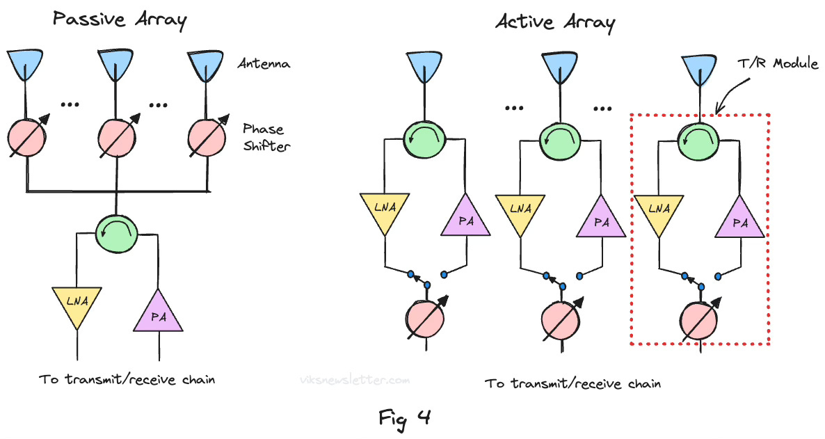
Passive arrays use a central transmitter and receiver amplifier to amplify radio signals, with a phase shifter at each antenna element. This was the primary design method in the early days of radar because implementing active circuits at each antenna element was prohibitively expensive. Passive arrays have limited functionality without amplitude control for each antenna. Features such as gain tapering cannot be implemented.
With the development of integrated circuits, active arrays have become a reality, with amplification and phase shift implemented using compact transmit/receive (T/R) modules at each antenna in the array. With complete control over the signal fed to each antenna, we can shape the radiated beam to meet the system's requirements.
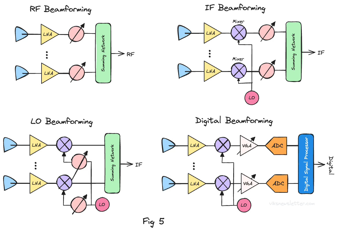
RF Beamforming
This has been the most common method of beamforming since the early days of phased arrays. The received and amplified signal from the antenna is phase shifted at RF frequencies. This approach is cost-effective and easy to implement due to its simplicity of the overall system. After combining signals from each antenna in the array, the beam is highly directive and rejects any interference before it reaches the digital transceiver. As a result, the transceiver's linearity requirements are significantly reduced.
IF and LO Beamforming
In this architecture, the phase shift to the antenna is implemented in the Intermediate Frequency (IF) range or using the Local Oscillator (LO). Phase shifters are easier to design for a narrow band of IF frequency, or in the LO approach, the phase shifter is not in the RF path to affect performance. However, there are a few downsides to this approach:
A mixer is required at each antenna element and that increases cost of the array
The mixer is subject to interference due to wide antenna beam (remember this is the raw antenna element before it is narrowed into a beam), and the resulting interference will propagate throughout the system.
For certain applications like in satellites, a very low noise local oscillator is required which eliminates the possibility of using integrated oscillators.
Digital Beamforming
This is the holy grail of antenna beamforming where all the phase shifting is implemented entirely in the digital domain by weighting each antenna signal received in the transceiver. The complexity and demands of implementing such a system is significant, but it provides the maximum flexibility in reconfiguring the antenna array dynamically.
By implementing all control in the digital domain, the array can be dynamically split up into sub-arrays to implement multiple beams, each with its own scan angle and sidelobe level. With the advent of artificial intelligence and machine learning, arbitrary antenna patterns can be synthesized on the fly to achieve the maximum signal-to-noise ratio in any radio interference environment to perform adaptive beamforming. Everything from a simple multi-layer perceptron network to a deep convolution neural network has been utilized to rapidly predict the antenna array weights required to optimally adapt the antenna with minimal computation. Lots of active research is current ongoing in this area.
Dishy McFlatface - A Case Study
Commercial low earth orbit (LEO) satellite-based broadband internet providers like Starlink and Amazon's similar initiative Project Kuiper, aims to enhance global connectivity by deploying thousands of interlinked satellites in a constellation.
Take Starlink's dish antenna (Dishy McFlatface or Dishy) for example. It consists of 1280 circular patch antennas each about a centimeter in diameter arranged in a hexgonal honeycomb. Each antenna is fed with a 12 GHz modulated signal carrying information that is to be transmitted. Depending on where the satellite is positioned in the sky, the generated beam from this array needs to be pointed exactly in a specific direction. To do this, each element in the array is fed with a progressively delayed version of the signal. to produce phase shifts and steer the beam.
Here's the challenge. The beam needs to be precisely transmitted to a satellite located 550 kilometers away that is moving at a speed of 27,000 kilometers per hour. When the satellite is out of line-of-sight, it needs to quickly switch over to the next available satellite in about four minute intervals.
The fact that this is even possible is the magic of the phased array antenna. The sheer amount of engineering in phased arrays can be staggering - involving integrated circuit design, electromagnetics, digital chips, signal processing - whose applications range from your pocket cellphone all the way to space.
It is amazing to say the least. I'll leave you with this fantastic video explaining how Dishy and satellite internet works.
⭐️ Key Takeaways
The direction of the beam generated from an antenna array is controlled by adjusting the phase shift between antenna elements.
Depending on the quantity of phase shift, the beam from a phased array is between broadside and endfire directions.
Modern phased arrays are almost entirely active arrays due to rise of low-cost integrated circuits.
Various beamformer architectures exist, with RF beamforming being the simplest from a system perspective and digital beamforming being the most complex but also the most versatile.
📚 References
“Phased Arrays — Part II: Implementations, Applications and Future Trends,” Parker et al., IEEE TMTT, Vol. 50, No. 3, Mar 2002.
“Silicon RFICs for Phased Arrays,” Rebeiz et al., IEEE Microwave Magazine, May 2009.
Figures in this article have been generated using Matlab’s Phased Array System Toolbox. You can try it out with a 30 day trial version and visualize a lot of what is described in this article.
The views, thoughts, and opinions expressed in this newsletter are solely mine; they do not reflect the views or positions of my employer or any entities I am affiliated with. The content provided is for informational purposes only and does not constitute professional or investment advice.


Wow - just discovered this Substack. And will be signing up!
Thanks for sharing