


The Rise of 800V Electric Vehicles and Role of Silicon Carbide
Exploring the engineering merits of higher voltage battery systems for next-generation EVs, and the benefits and challenges involved in using high bandgap silicon carbide transistors

A quick note: I will be at the International Symposium of Solid State Circuits (ISSCC) held in San Francisco from February 16—20th. Reply to this email and let me know if you will be there too. I’m always happy to meet people and learn about the things you’re working on.
Vehicles using internal combustion engines can refill in less than 5 minutes. However, electrification of automobiles is a current priority.
A 150-250 kW DC fast charging station can fully charge an electric vehicle (EV) like the Tesla Model S in 30 minutes. However, fast charging is costly.
A cheaper 7 kW charger that works with residential electrical systems takes roughly 12 hours, whereas a 22 kW public charger often found in office parking lots takes about 6 hours.
The only cure to range anxiety is to have longer range electric cars that charge faster, for cheaper.
The voltage of the battery pack is an important consideration while designing EVs. Traditionally, EVs have used 400 V systems for a variety of reasons, including the availability of high-voltage transistors, safety issues, insulation, and the ubiquity of 400 V charging stations.
Today, many EV manufacturers have already moved to 800 V systems. There are numerous benefits to doing so, which we will explain in detail. However, a higher voltage system entails a complete overhaul of crucial automobile electronics, traction inverters, motors, and charging infrastructure.
In this article, we'll look at why transitioning from 400 to 800 V battery systems is beneficial, and why silicon carbide (SiC) is a good candidate but riddled with challenges.
Some of the content is paywalled. Please consider getting a paid subscription to access the whole post.
Fundamental limitations of 400 V battery systems
Configuration
Transistor technology
Current-limited charging rate
Benefits of 800 V battery systems
Faster charging
Improved cable systems
Battery management and traction motors
🔒SiC transistors for 800 V systems
🔒Advantages for EVs
🔒Manufacturing difficulties
🔒Where are we now?
🔒References
Read time: 14 mins
P.S.: If you're new to power electronics in electric vehicles, you can check out my earlier post for an introduction.

Fundamental Limitations of 400 V Systems
Configuration
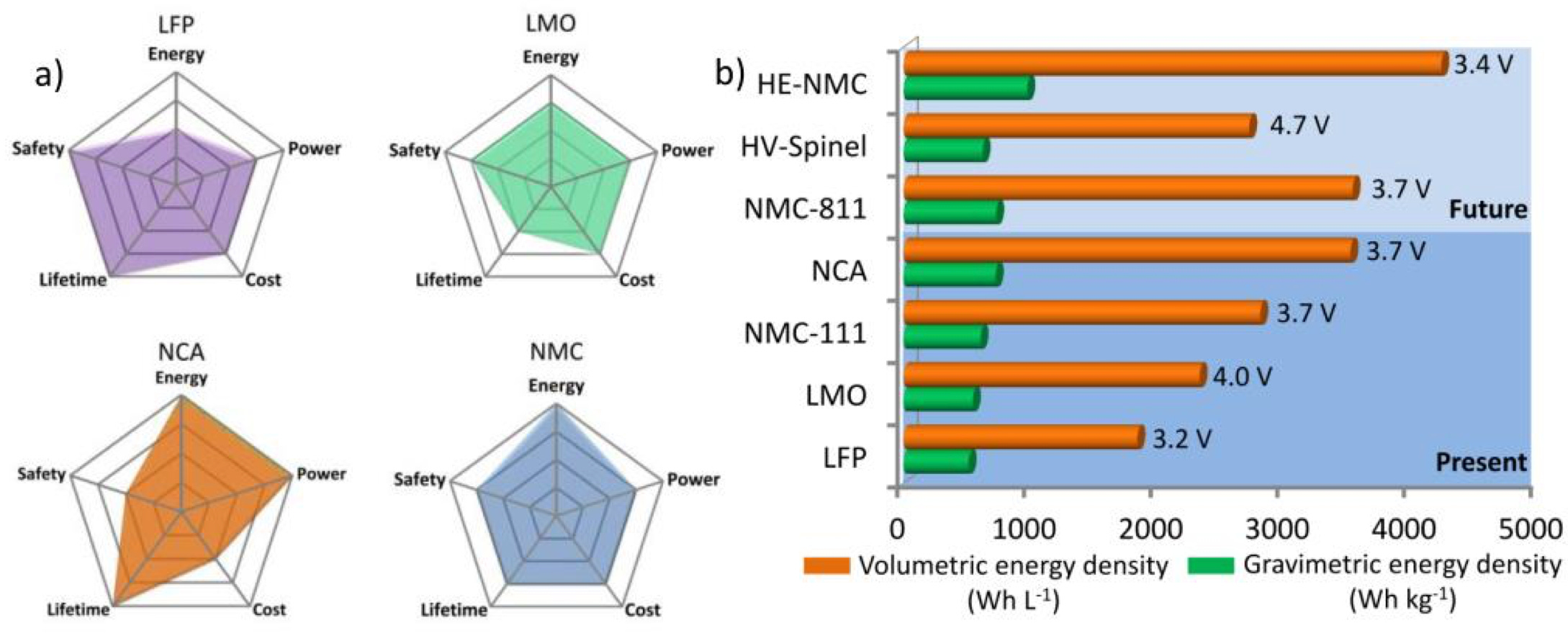
Lithium-ion is the preferred battery technology for EVs due to its high energy density. They provide a nominal output ranging from 3.2 V to 4.2 V per cell, depending on the cell chemistry — Lithium Iron Phosphate (LFP), Lithium Manganese Oxide (LMO), NMC (Nickel Manganese Cobalt), or NCA (Nickel Cobalt Aluminum), and each has different tradeoffs in terms of energy density, power output, cost, lifetime, and safety. Their physical shape (cylindrical, prismatic, or pouch) influences their thermal dissipation capabilities.
In an EV, multiple identical batteries are connected in series, resulting in a total voltage that is around 400 V. Depending on the amount of current consumed from the battery, many parallel banks of battery cells are used to generate the required total power output. The series-parallel battery combination is denoted by XsYp, where X is the number of series cells and Y is the number of parallel banks.
For example, a newer generation Tesla Model 3 Long Range Dual Motor has 96 series cells, and 46 parallel cells (or 96s46p) — a total of 4416 cells. It provides a nominal voltage of 357 V and 75 kWh of usable capacity. You can view many battery configurations on ev-database.org.
Transistor Technology
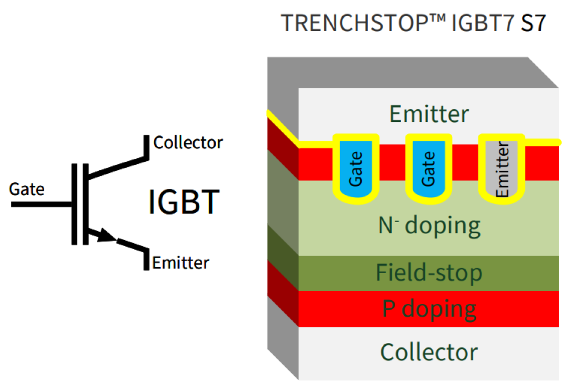
Insulated Gate Bipolar Transistors (IGBTs) have primarily powered the EV revolution while also serving as dependable workhorses in industrial power electronics. Since the 1980s, IGBTs have been a cost-effective, mature, and dependable transistor for controlling industrial motors.
These transistors are a perfect fit for traction inverters in EVs, where they are used in switching mode to convert DC to AC power needed to drive the motors. They can handle high voltages, have great reliability and are low cost. Their main disadvantage is their switching speed, which is limited to 20-50 kHz.
Current-limited Charging Rate
There is an upper limit to the charging rate possible with 400 V battery systems. It is best look at this with a practical example.
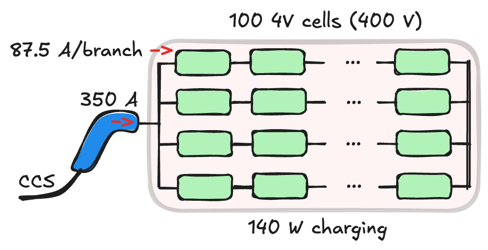
Consider an EV battery system with 100 series, 4 parallel banks (100s4p) with each Li-ion battery providing a 4 V output, with a peak charging current capacity of 150A for each battery cell. With 100 Li-ion cells each providing 4 V output in series connection, the resulting battery system is 400 V. Since there are 4 parallel banks, we should be able to charge at 4*150 A = 600 A.
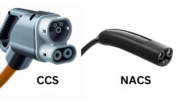
The Combined Charging System (CCS) connector — a common standard for EV charging — is rated to a maximum of 1000 V and 500 A (5 kW) and cannot support a 600 A current through it. The North American Charging System (NACS) is another standard becoming a more popular with Tesla charging infrastructure. Regardless, they are all current limited to 500—650A.
At the higher end of current levels, liquid cooling systems are often required to maintain efficient energy transfer and not lose energy to heat dissipation in copper cables. This adds to the complexity and cost. About 350 A is a reasonable current level that these charging standards support without extra effort.
In a 400 V battery system limited by the CCS connector, the total charging power is 400 V x 350 A = 140 kW, which is representative of charging at a 150 kW DC fast charge station. The current drawn by each cell is 350/4 A or 87.5 A, which is far lower than the current limit of the battery cell (in this example, 150 A). Drawing much lower current compared to what the cell can handle creates lower heat and prolongs the life of the Li-ion cells, which in this case is actually an advantage.
However, a 400 V system is inherently limited by the current capacity of the charging cable. Going to 250 kW fast charging provided by the Tesla Supercharger infrastructure is not advantageous because the power draw will cap out at 150 kW due to current limitations. This simply means that we can’t charge the vehicle any faster by increasing the power capabilities of the charging station.
To get improvements in charging speeds and other benefits, we need to transition to 800 V systems. But there are also downsides which we will see next.
Benefits of 800 V Battery Systems
Faster Charging
Let's reorient the battery to an 800 V configuration and redo these calculations, and also see what other benefits exist in moving to higher voltages.
Now we will use 200 series, 2 parallel banks (200s2p) as the battery configuration. The physical size of the battery system is the same because we will have 400 cells in all. We now operate at 800 V due to 200 series cells putting out 4 V each. However, the maximum current supported by the system is 150 A * 2 parallel branches = 300 A.
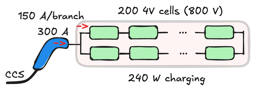
If we charge the battery at the maximum rate supported by the cells which is 300 A, the charging power is 800 V x 300 A = 240 kW. At this power level, Tesla Superchargers can provide their full DC fast charge output to the battery system enabling faster charging. Coincidentally, 250 kW Tesla Superchargers are now available for use to non-Tesla EV manufacturers, opening the door for faster charging as car makers switch to higher voltages in their battery systems.
Here is the takeaway: doubling the voltage lowers current for a constant charging power. Or alternatively, voltage doubling at a constant current level doubles the charging power (P=VI).
The disadvantage is that the battery cell is charged at maximum current, which means that thermal dissipation and premature aging of the cells must be considered.
Another subtle implication is that charging current cannot be raised indefinitely with higher power chargers, even when operating at 800 V, without eventually being hitting a wall where the battery cannot support any more current through it.
Still, there are many modern car makers switching over to 800 V systems for better charging performance. Here are some examples.
Chinese car maker Zeekr is releasing its 007 model in 2025 with a 311 mi (500 km) range that uses an 800V battery architecture and promises to charge from 10% to 80% SoC in about 10 minutes using 500 kW charging. This could possibly be the fastest charging EV in the market today.
Lucid Air is an another example of a high voltage battery system designed to operate at 900V. It achieves 10-80% SoC in about 25 minutes with a 150 kW charging station.
The 2024 Porsche Taycan 4S with 800V battery systems charges from 5-80% SoC in about 16 minutes and is capable of fast charging up to a rate of 320 kW.
The recently released 2025 BYD Han L sedan uses a 945V architecture and uses a dual gun charging system to charge from 16-80% SoC in 10 minutes (odd choice of numbers.)
Reduced Copper Weight
Even if charging speed and higher currents are not the primary concern as in the case of low-end EVs, a higher voltage architecture significantly lowers the cost and weight of copper cabling involved.
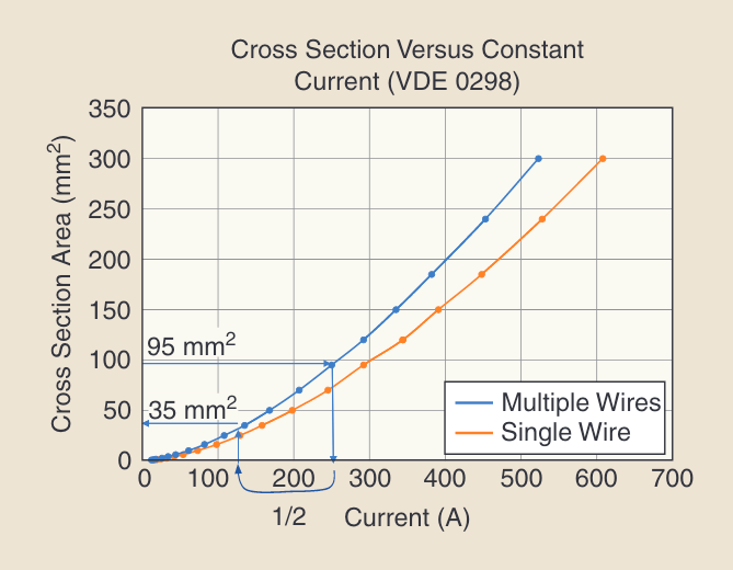
For example, a 250 A charging current at 400 V requires the wiring to have a cross section of 95 mm2, but 125 A at 800 V requires only a cross section of 35 mm2. The results in a reduction of copper weight in the main wiring harnesses by nearly a factor of 3. Considering that EVs require 3-4 times more copper than an internal combustion engine driven vehicle, reducing the amount of copper used and its corresponding weight has a major impact on the efficiency and range of the EV.
The usage of lower gauge copper in charging stations also reduces the weight of cables which should be under 23 kg (or 50 lbs). This is set by the National Institute for Occupational Safety and Health (NIOSH) for lifting tasks to minimize injury risk. Notice how this coincides with airline baggage limits for the same reason. Also, wires with smaller cross-sectional area are easier to bend and route in tight spaces leading to more space-efficient routing.
Battery Management and Traction Motor Design
Moving to an 800 V system requires twice as many battery cells connected in series as 400 V systems. The battery management system's duty is to assure the battery pack's health, dependability, and operation, and doubling the voltage sensing channels increases its cost and complexity.
The traction motor used to drive the wheels entirely benefits from moving to higher operating voltages. An 800 V drive increases the electromagnetic performance of the motor, and its power density (how much power it can deliver in a given volume), and also allows it to run at higher speeds. At higher voltages, lower currents in the stator lead to lower copper losses. Lower current implies that the gauge of wire used in the stator can be made thinner, which decreases the overall weight and size of the motor.
The greatest risk for motors in higher voltage designs is partial discharge (PD). This is a phenomenon in which the transient voltage between wires, which can reach up to 1,500 V during the switching operation of the traction inverter, degrades the wire insulation. This should be carefully designed for.
Silicon Carbide for 800 V applications
With 800 V battery packs, switching transistors in the traction inverter need to also support higher voltages. SiC has been long touted as a promising alternative.
After the paywall, we will discuss why SiC is good, the challenges involved and the current state of SiC in EVs.