A Preliminary Guide to Antenna Arrays
Why arraying creates a narrow beam, how to choose antenna elements and array geometry, and understanding gain tapering and mutual coupling problems. Also check out these gigantic antenna arrays!
Thanks for reading! If you’d like to suggest topics, have questions or just want to say hello, contact me via email, and follow me in LinkedIn/X for behind-the-scenes content.
If you enjoyed this, please share it on social media or your professional network. It really helps to grow this newsletter! 🙏
Antenna arrays have been the foundation of radar for decades, and they have recently been used in commercial communication systems for 5G beamforming. This article discusses the fundamentals of antenna arrays. It will serve as the foundation for subsequent discussions on phased arrays and beamforming.
You will learn:
How antenna arrays create narrow beams
What is the impact of antenna type and array geometry
How gain tapering improves array performance
Detrimental effects of mutual coupling and how to address it
Finally, you can check out some amazing gigantic antenna arrays used for radio astronomy along with YouTube links for video goodness!
Let's dive in!
Arraying Antennas to Create Narrow Beams
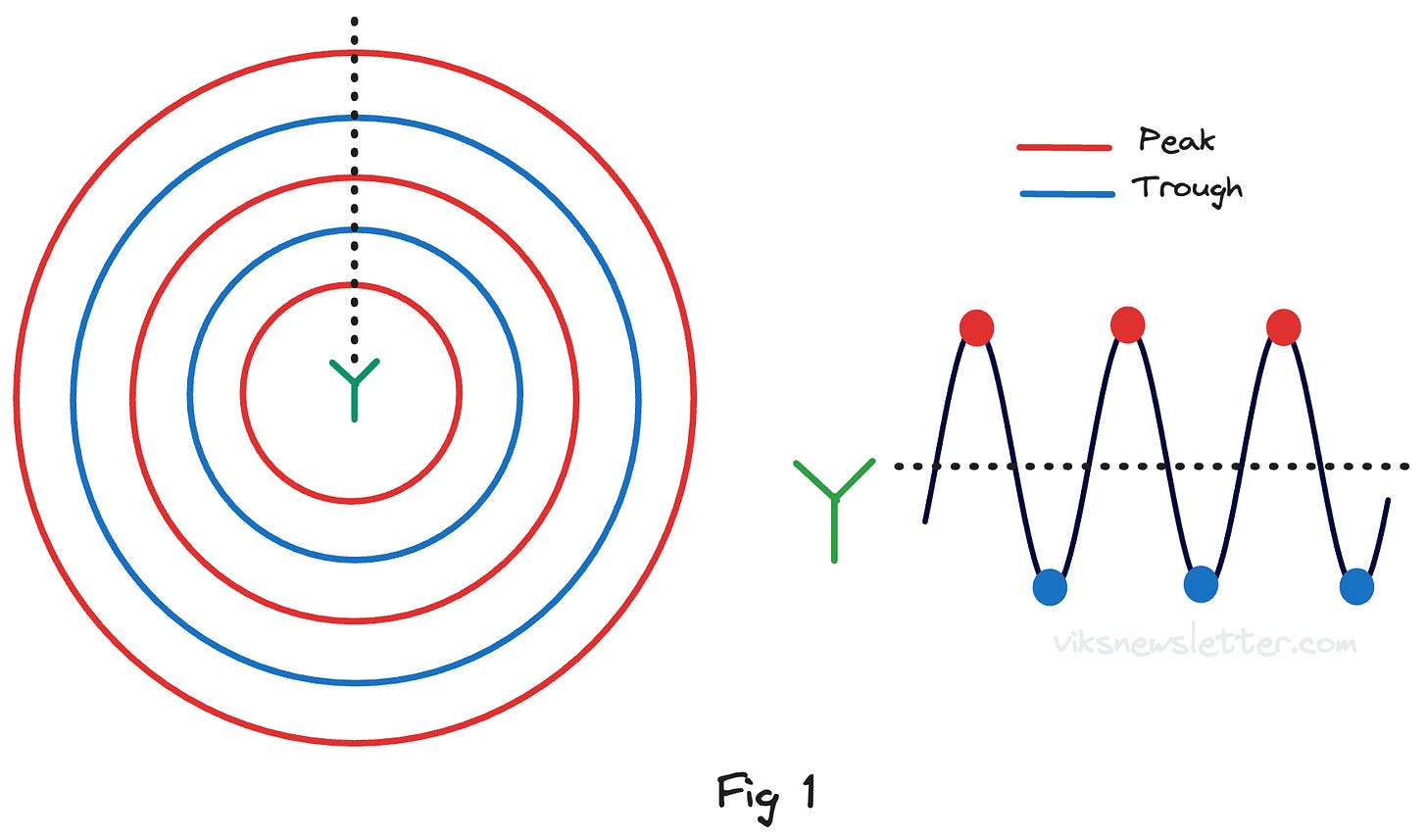
Assume we have an isotropic antenna that emits a sine wave in space at a given wavelength. The radiation pattern from such an antenna is omnidirectional, i.e., it radiates in all directions. As shown in Figure 1, the red circles represent sine wave peaks, while the blue circles represent troughs. The distance between a red and blue circle equals half a wavelength.
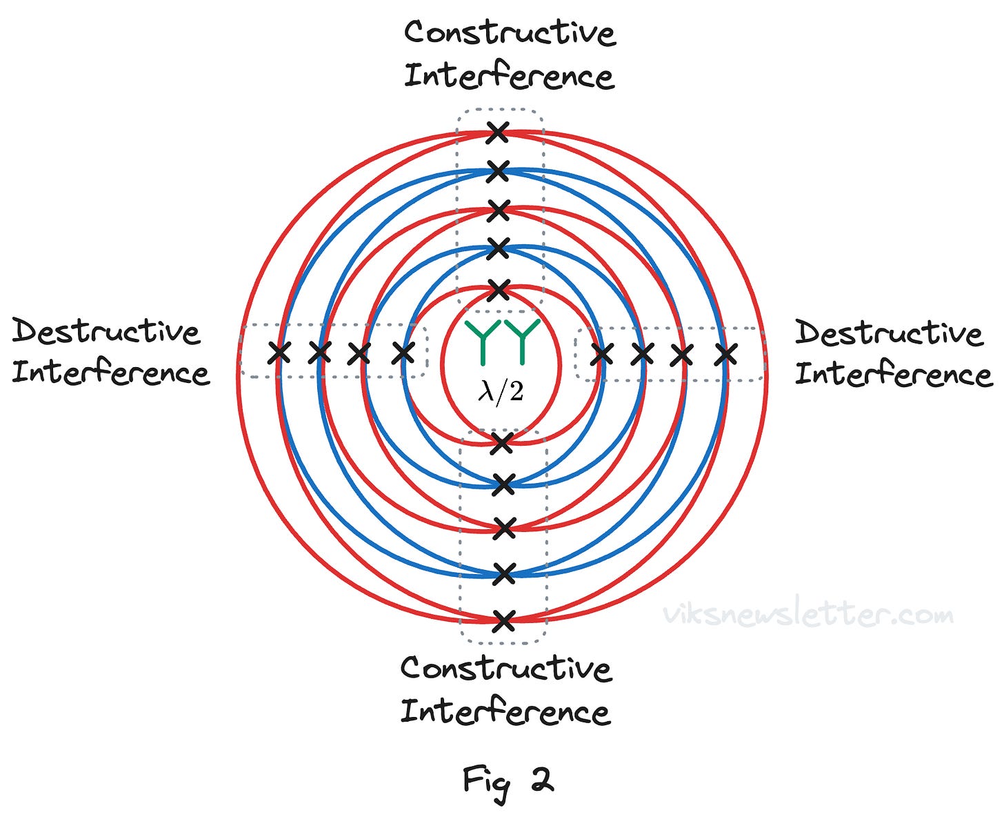
Clearly, this radiation pattern is not as directional as we would like. To direct the antenna beam in a specific direction, place another similar isotropic antenna exactly half a wavelength away from the original one. Feed both antennas with signals of equal amplitude and phase. Then observe how the radiation patterns of these two antennas interact in space.
You notice that radiation circles of the same color intersect along the vertical axis, causing "constructive interference." This means that the signals from each antenna combine to generate a stronger signal. Along the horizontal axis, the red and blue circles intersect resulting in "destructive interference." The signals from each antenna cancel out, resulting in low radiation in that direction. Simply placing two identical antennas at a fixed distance apart results in an antenna radiation pattern that is narrower than the original single antenna pattern.
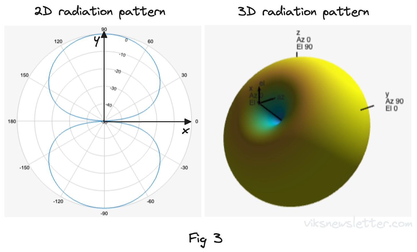
Figure 3 depicts the antenna gain diagram on the x-y plane, looking along the z-axis. The azimuth pattern of the antenna represents how strong the antenna signal is as you move around it. When there is constructive interference, the radiation is strongest along the Y axis, whereas destructive interference produces a radiation null along the X axis.
However, the radiation pattern remains isotropic along the y-z plane due to the absence of signal cancellation. Figure 3 depicts the 3D radiation pattern for this antenna array. It resembles a donut because the linear array's interference pattern produces a null only in one direction.
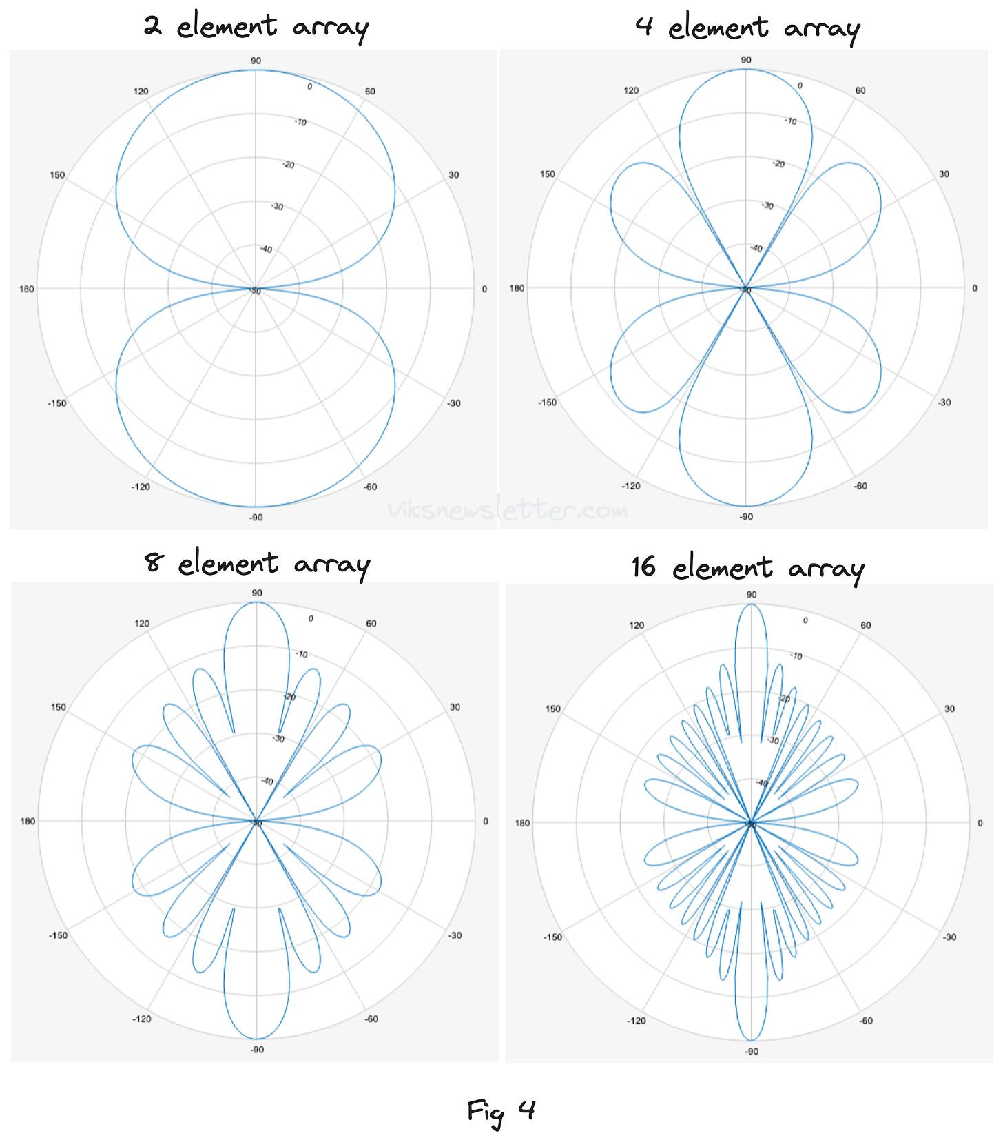
Adding more antenna elements to the array results in a narrower beam. Figure 4 illustrates the antenna patterns for two, four, eight, and sixteen element linear arrays, with each antenna separated by a half wavelength. The main beam along the +/- 90 degree direction narrows as the number of elements increases, and radiation along the 0/180 degree directions always generates a null due to wave cancellation.
In higher element arrays, "side lobes" or unwanted radiations occur in specific directions due to imperfect wave cancellation, and their number increases with the number of antennas in the array. There is still a null between each lobe, which engineers use cleverly to improve signal-to-noise ratio. We will go into greater detail about this in a future article on adaptive beamforming.
Two Dimensional Antenna Arrays
So far, we have produced radiation patterns that are more directed in a single plane. The radiation pattern continues to emit in all directions in a perpendicular plane, as shown in Figure 3 with the donut 3D radiation pattern of a two element array.
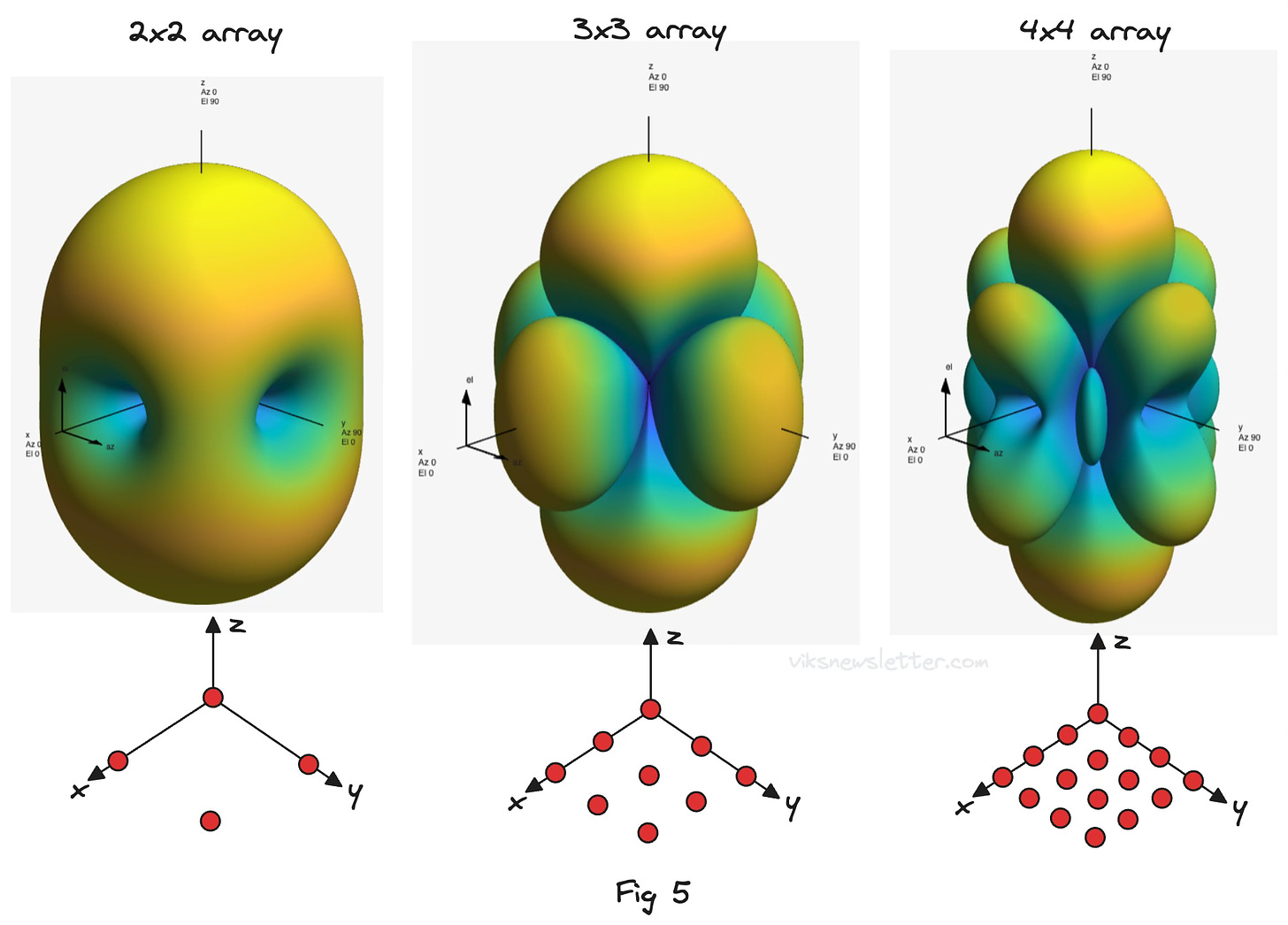
To narrow the radiated antenna beam in both directions, we require a two-dimensional antenna array, with a NxN element rectangular array being a popular choice. Constructive and destructive interference patterns occur along two perpendicular planes. This produces a directed conical beam with side lobes in three dimensions. Figure 5 depicts the radiation pattern of a 2x2, 3x3, and 4x4 rectangular antenna array with isotopic antennas spaced half wavelength apart in both directions.
In practice, a 4x4 element array is common, and it can even serve as the foundation for larger element arrays or arrays with multiple beams for multiple-input, multiple-output (MIMO) systems. The 4x4 array offers a good compromise that allows feed structures for the antenna array to be designed with minimal loss. Keep in mind that the array size increases linearly in both directions. As a result, the transmission lines connecting to these antennas are already several wavelengths long. It's important to consider their losses.
Other Considerations
When working with antenna arrays, there are several other design considerations and practical implementation issues to address.
Choice of Antenna Element
So far, our analysis has only included isotropic antennas. If a sharper beam is required, using an antenna element with a focused radiation pattern immediately improves the overall directivity of the antenna array. The ideal element for the array is chosen based on the application and factors such as the desired radiation pattern, polarization, and size.
Here are some popular antenna choices for arrays:
Dipole Antennas: Widely used for their relatively small size compared to operating wavelength, simple structure and omnidirectional radiation pattern in the H-plane (donut shaped). They are well suited for high density arrays.
Patch Antennas: Popular choice for phased array systems due to its planar geometry and ease of integration with active components for beam steering.
Slot Antennas: Useful when antenna arrays need to be integrated into the surface of an object (conformal array) like an aircrafts exterior surface. Their radiation characteristics are similar to dipole antennas.
Horn Antennas: Used when wide operating bandwidth is required, or while feeding an array of parabolic dishes. They are stable and often used to calibrate other antenna arrays.
Yagi-Uda Antennas: Used when there is a need to have significant control over the radiation pattern and where high directivity is needed. They are physically large and not particularly useful in dense arrays.
Log-Periodic Antennas: Used when broad frequency coverage is required, and often used in spectrum monitoring or electronic warfare.
Array Geometries
Antennas can be arranged in geometric patterns other than linear or rectangular shapes, depending on the application and design specifications. The rectangular array is still a popular choice when implementing planar antenna array systems into communication systems, but other shapes are possible.
Circular Arrays: Antennas arranged in a circle produce directional beams that can be steered in the azimuth plane. A useful application is in a ship's navigation system, where the antenna array must scan horizontally rather than vertically.
Cylindrical Array: Consider this a linear array made up of circular arrays. It scans 360 degrees in the azimuth plane and has elevation control (up and down). They're useful for electronic warfare, radar, and navigation.
Spherical Array: Useful for forming and steering beams in any direction in 3D space. Suitable for satellite communications and advanced radar.
Conformal Array: Antenna elements are placed along a curved surface to avoid disrupting the aerodynamics or aesthetics of an aircraft or vehicle.
Gain Tapering
In our antenna array analysis, each antenna received equal amplitude and phase signals. In a separate article on phased arrays, we will discuss how to introduce phase shifts between antenna elements. However, carefully adjusting the amplitude levels (but keeping the same phase) can help improve array performance by reducing side lobes in the radiation pattern. Here is how.
Because the peripheral antenna elements in the array lack a neighboring element to completely cancel out signals in specific directions, they are the primary contributors to side lobes in a radiation pattern. By lowering the signal level fed to the peripheral antenna elements, side lobe levels can be reduced significantly. This is known as gain tapering.
The trade-off with gain tapering is that the main lobe becomes wider, reducing the antenna array's resolution. However, reducing overall interference at the expense of slightly lower main lobe gain improves the antenna system's overall signal-to-noise ratio.
Mutual Coupling
We have always considered antenna elements to be independent of one another. However, when they are close together, the field emitted by one antenna induces currents in the neighboring antennas. This has the following implications:
Impedance Changes: The induced current on an antenna alters its input impedance, affecting the power delivered to each antenna due to mismatch losses.
Radiation Distortion: When elements are not fed with equal amplitude, the radiation pattern gets significantly distorted. The main lobe will point in the wrong direction, and the side lobe level will increase.
Polarization Changes: If the elements in the array radiate with a specific polarization, mutual coupling can result in unwanted radiation components and, eventually, polarization losses.
Given the half-wavelength spacing requirement between antenna elements, preventing mutual coupling can be a challenge. Increasing the spacing would reduce mutual coupling, but it would also result in unwanted side lobes known as grating lobes caused by improper signal cancellation in space.
Implementing decoupling networks between antennas is possible, but they add complexity to the array's design. Isolation elements, such as absorbers, can be placed between array elements, but this is rarely practical in a planar array.
Ultimately, the antenna array is optimized for mutual coupling effects using computational electromagnetic methods, with feed structures and radiating elements positioned to produce the desired radiation pattern.
Gigantic Antenna Arrays
The Square Kilometer Array Observatory will be the biggest arrayed radio telescope on earth over the coming decade. They are going to be built in remote regions of Australia and South Africa to unlock the mysteries of our universe. The array itself consists of hundreds of parabolic dishes, each one six stories tall. Check out this video!
The Atacama Large Millimeter/submillimeter Array (ALMA) in northern Chile is currently the largest radio telescope in the world and consists of 66 parabolic dish antennas, most of them about 12 meters in diameter operating across the 30 GHz to 1 THz frequency band. It cost $1.4 billion to build and is the most expensive ground based telescope in operation. Check out the documentary on ALMA.
The Very Large Array (VLA) telescope in New Mexico consists of 27 parabolic dishes each one 25 meters in diameter and weighing 230 tons. Even more amazing is that they can be moved around on railroad tracks to form different configurations to cluster them in a 0.5 square mile area, or spread them out over 22 miles. Check out the live feed, and a nice documentary on the VLA.
⭐️ Key Takeaways
Arraying antenna elements creates a more directed radiation pattern.
Constructive and destructive interference enhance signals in some directions while cancelling it out in others.
Higher the number of antennas in an array, the more directed the beam.
Choice of array pattern and radiating element depends on the application.
Using antennas with higher directivity increases overall array directivity.
Gain tapering can be used to reduce side lobes and increase SNR.
Mutual coupling is an unavoidable effect that needs to be considered in design.
📚 Resources
Don Parker and David Zimmermann, “Phased Arrays — Part I: Theory and Architectures,” IEEE Trans. Microwave Theory and Techniques, Vol. 50, No. 3, Mar. 2002.
Figures in this article have been generated using Matlab’s Sensor Array Analyzer app. You can try it out with a 30 day trial version and visualize a lot of what is described in this article.
The views, thoughts, and opinions expressed in this newsletter are solely mine; they do not reflect the views or positions of my employer or any entities I am affiliated with. The content provided is for informational purposes only and does not constitute professional or investment advice.




Love the 3D Viz!
Hi Vikram, would like to know which type of antenna and antenna designs are used for mobile devices let's say for wifi radio .please help to understand!